
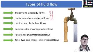
Type of Flow
Enroll to start learning
You’ve not yet enrolled in this course. Please enroll for free to listen to audio lessons, classroom podcasts and take practice test.
Interactive Audio Lesson
Listen to a student-teacher conversation explaining the topic in a relatable way.
Understanding Flow Types
🔒 Unlock Audio Lesson
Sign up and enroll to listen to this audio lesson

Today, we'll discuss fluid flow through pipes, particularly focusing on the types of flow—laminar and turbulent. Who can explain the difference between these two types?

Laminar flow is when the fluid flows in parallel layers, while turbulent flow is when the fluid mixes chaotically.
Exactly! Would you like to tell us how we determine the flow type?

I think we use the Reynolds number to classify them. If Re is below 2300, it's laminar, and above 4000, it's turbulent.
Great! Let's remember this: L for Laminar goes with Re < 2300. T for Turbulent goes with Re > 4000. Now, what about the range between 2300 and 4000?

That would be the transition flow?
Correct! Let's summarize: Laminar with Re < 2300, Turbulent with Re > 4000, and Transition in between.
Energy Losses in Pipes
🔒 Unlock Audio Lesson
Sign up and enroll to listen to this audio lesson

Shifting gears, let's discuss energy losses incurred during pipe flow. Who can explain what we mean by major and minor losses?
Major losses are primarily due to friction along the pipe walls, while minor losses typically occur from fittings and obstacles.
Exactly! We classify these closely. Major losses include losses from straight piping due to friction, and minor losses occur from bends, contractions, and exits. Can anyone think of an example of a minor loss?

A valve or a bend in the pipe would be an example of a minor loss?
Perfect! So remember, M for Major losses are from friction, while M for Minor losses refers to fittings. Let's summarize: Major losses are frictional losses along the pipe and Minor losses are caused by fittings and bends.
Real-World Applications
🔒 Unlock Audio Lesson
Sign up and enroll to listen to this audio lesson
Now, let's talk about real-world applications. How are these principles applied in water supply systems?
In water supply systems, understanding these losses helps in designing efficient systems where we minimize pumping costs and energy wastage.
Exactly! Companies might use software to predict pressures, flow rates, and energy losses throughout the system. Anyone thought of how this can impact design decisions?
Proper pipe sizing can reduce the required pump power, ultimately saving costs and improving efficiency.
Great insight! Remember, efficient water systems equate to better design minimizing energy losses.
Introduction & Overview
Read summaries of the section's main ideas at different levels of detail.
Quick Overview
Standard
The section explains the classification of flow types as laminar and turbulent based on Reynolds numbers. It also emphasizes energy losses in pipes due to friction and fittings, introducing concepts like major and minor losses, and discusses practical applications in water supply systems.
Detailed
The flow of fluids in pipes can be classified mainly into two types: laminar and turbulent. The Reynolds number (Re) is critical in determining the flow type; flows with Re < 2300 are considered laminar, while those with Re > 4000 are turbulent. In between these values, there is a transition state. This section also delves deep into the losses incurred during flow through pipe fittings, which are categorized into major losses (due to friction) and minor losses (due to fittings). The concepts of hydraulic gradient lines, energy gradient lines, and the application of Bernoulli's equation and momentum equations for analyzing flow in pipe systems are further discussed. The significance of minimizing energy losses in water supply systems is underscored, alongside experimental methods to quantify these losses.
Youtube Videos


Audio Book
Dive deep into the subject with an immersive audiobook experience.
Understanding Flow Types
Chapter 1 of 4
🔒 Unlock Audio Chapter
Sign up and enroll to access the full audio experience
Chapter Content
When discussing flow in pipes, we categorize it as either laminar or turbulent flow based on the Reynolds number. The Reynolds numbers quantify the ratio of inertial forces to viscous forces in the fluid. A Reynolds number less than 2300 indicates laminar flow, while a Reynolds number greater than 4000 indicates turbulent flow. Flow in the range of 2300 to 4000 is considered transitional.
Detailed Explanation
Flow in pipes can be classified into two main types based on the Reynolds number: laminar and turbulent. The Reynolds number is a dimensionless quantity that reflects the relationship between the inertia of the flow and its viscosity. For laminar flow, which occurs when the Reynolds number is less than 2300, the fluid flows in smooth, parallel layers with little to no mixing. In contrast, turbulent flow occurs when the Reynolds number exceeds 4000, characterized by chaotic changes in pressure and velocity, and mixing of different fluid layers. Values between 2300 and 4000 indicate a transitional flow where characteristics of both types may be observed.
Examples & Analogies
Imagine a calm river flowing gently; the water moves in layers, much like laminar flow in pipes. Now, think about a water park where the water slides create splashes and turbulence. The calm river represents laminar flow, while the chaotic water park symbolizes turbulent flow.
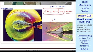
Visualizing Turbulence
Chapter 2 of 4
🔒 Unlock Audio Chapter
Sign up and enroll to access the full audio experience
Chapter Content
Turbulence can be visualized using vortex formations and eddies, which occur in greater numbers in turbulent flows. Laboratories today can measure these turbulent structures to understand and quantify energy dissipation caused by turbulence.
Detailed Explanation
In turbulent flows, you can often see vortex formations and eddies—spiral-like movements that occur when fluid flows over an obstacle or encounters uneven surfaces. These features lead to energy dissipation as they create friction and drag within the flow. Modern fluid mechanics laboratories have tools that allow researchers to visualize and measure these turbulent structures, helping to quantify how much energy is lost due to turbulence, which is a central concern in fluid flow analysis.
Examples & Analogies
Think of how a car engine works. When fuel mixes with air and ignites, it creates rapid movement and turbulence inside the cylinder. That turbulence helps in mixing the fuel and air thoroughly but can also generate heat and energy loss, much like how vortices in turbulent flow lead to energy dissipation in pipes.
Applications of Flow Types
Chapter 3 of 4
🔒 Unlock Audio Chapter
Sign up and enroll to access the full audio experience
Chapter Content
Understanding flow types is crucial for designing pipe systems, especially in applications like water supply schemes, where losses in energy and efficiency need to be minimized.
Detailed Explanation
The knowledge of whether the flow is laminar or turbulent has significant implications for the design of plumbing and piping systems. Engineers must consider how much energy will be lost due to friction and turbulence when designing water supply networks. By knowing the flow type, they can choose appropriate pump sizes, pipe diameters, and configurations to minimize energy losses and ensure efficient water delivery to various locations.
Examples & Analogies
Picture setting up a series of water slides at a water park. If the slides are too steep (turbulent flow), water splashes everywhere, and it might not get to the bottom effectively. However, if they are gently sloped (laminar flow), the water glides smoothly without splashing. You want to find the right balance in designing the slides to ensure a fun experience without losing too much water!
Measuring Turbulence and Energy Losses
Chapter 4 of 4
🔒 Unlock Audio Chapter
Sign up and enroll to access the full audio experience
Chapter Content
Experimental setups can measure pressure differences across pipes to quantify energy losses due to turbulent flow and minor losses at fittings, bends, or junctions.
Detailed Explanation
To understand energy losses in pipe systems, engineers set up experiments that measure the pressure difference between two points in a pipe. This data allows for calculations of flow velocities and, in turn, quantification of energy losses. These losses can be attributed to friction in the pipes (major losses) as well as to fittings, bends, and valves in the systems (minor losses). By carefully analyzing this data, engineers can optimize designs to reduce energy consumption.
Examples & Analogies
Consider your home's plumbing. When you turn on the shower and nothing happens, it might be because of a kinked hose or clogged pipe causing a pressure drop. By understanding how to measure pressure losses and where they occur, plumbers can fix these issues, ensuring a strong and steady flow of water without wasted energy.
Key Concepts
-
Flow Types: Laminar and turbulent flow are classified based on Reynolds number.
-
Reynolds Number: A critical value that separates laminar and turbulent flow.
-
Major Losses: Losses in energy due to friction along pipe walls.
-
Minor Losses: Losses in energy due to fittings and other changes in flow direction.
Examples & Applications
In a water supply system, if a pump is required to maintain flow and pressure, understanding the total energy losses helps in sizing the pump accurately.
When using PVC elbows instead of sharp bends in a pipeline, we can reduce the minor losses from fittings.
Memory Aids
Interactive tools to help you remember key concepts
Rhymes
Laminar's smooth, turbulent's rough; know your Re's, that's the tough stuff.
Stories
Imagine a serene pond for laminar flow, with calm ripples. Now picture a rushing river for turbulent flow, chaotic yet powerful.
Memory Tools
Remember 'M for Major, M for Minor': Major losses from friction, Minor from fittings.
Acronyms
L-T-T
Laminar-Turbulent-Transitional for Re classification.
Flash Cards
Glossary
- Laminar Flow
Flow characterized by smooth and orderly movement in parallel layers.
- Turbulent Flow
Flow characterized by chaotic and irregular fluid movement.
- Reynolds Number
A dimensionless number used to predict flow patterns in different fluid flow situations.
- Major Losses
Energy losses in flowing fluids due to friction along pipe walls.
- Minor Losses
Energy losses in a pipe system due to sudden changes in flow direction or area.
- Hydraulic Gradient Line
A line that represents the potential energy of the fluid at various points in the system.
- Bernoulli’s Equation
An equation that describes the conservation of energy in fluid flow, relating pressure, velocity, and elevation.
- Momentum Equation
An equation based on Newton's laws that relates forces and the momentum of a flowing fluid.
Reference links
Supplementary resources to enhance your learning experience.