
Importance of Energy Gradient Lines
Enroll to start learning
You’ve not yet enrolled in this course. Please enroll for free to listen to audio lessons, classroom podcasts and take practice test.
Interactive Audio Lesson
Listen to a student-teacher conversation explaining the topic in a relatable way.
Introduction to Energy Gradient Lines
🔒 Unlock Audio Lesson
Sign up and enroll to listen to this audio lesson

Today, we will discuss energy gradient lines, which are vital for understanding fluid behavior in pipelines. Can anyone tell me what these lines represent?

Are they about where the pressure decreases in a fluid flow?
Close, they actually represent the available energy per unit weight of fluid at various points. Let's remember this by using the mnemonic 'PEV' for Potential Energy Visualized.

What applications do these energy lines have?
Great question! They help in calculating energy losses in pipe systems, which is essential for effective engineering design.

So they play a role when we use Bernoulli's equation?
Exactly! We apply the Bernoulli equation along these energy gradient lines to understand how pressure and energy change throughout the flow.
Calculating Energy Losses
🔒 Unlock Audio Lesson
Sign up and enroll to listen to this audio lesson

Let’s dive deeper into calculating energy losses. What contributes to energy loss in a pipeline?

Friction is one major factor, right?
Yes! Friction against the pipe walls leads to energy losses, and we visualize these losses using energy gradient lines.
And how do we quantify that?
We can use manometers and Bernoulli's principle to determine the pressure differences, which then inform us about head losses.
Can you give an example of that?
Absolutely! If we have a specific flow rate in a pipe, knowing the diameter and friction factor can help us calculate the total energy loss from the pump to the exit of the system.
Introduction & Overview
Read summaries of the section's main ideas at different levels of detail.
Quick Overview
Standard
The discussion emphasizes the role of energy gradient lines or hydraulic gradient lines in determining the energy losses during fluid flow in pipes. The understanding of these concepts is vital for proper design and analysis in civil engineering systems.
Detailed
Importance of Energy Gradient Lines
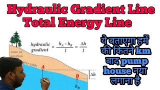
In fluid mechanics, energy gradient lines, often referred to as hydraulic gradient lines, play a crucial role in understanding fluid flow behavior in pipes. They allow engineers to visualize the energy changes that occur as fluid moves through a given system. The section explains how energy gradients are essential for calculating head losses due to friction and other factors in pipe networks. The relevance of these gradients extends to various applications, including designing water supply systems, where energy losses must be minimized for efficiency.
Key Points:
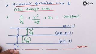
- Definition: Energy gradient lines represent the potential energy of fluid in a pipe system.
- Applications: Essential for analyzing losses in pipe fittings, vital in systems like water distribution.
- Calculations: Help engineers use Bernoulli's equations effectively to calculate pressures, velocities, and energy losses at various points in a pipeline.
- Real-World Application: Use in designing efficient water supply and drainage systems, understanding how to position pumps and tanks to counteract losses encountered in a network.
Youtube Videos
![Hydraulic and Energy Grade Line ? with animation [ HGL and EGL ]](https://img.youtube.com/vi/moI4DQNirAw/mqdefault.jpg)


Audio Book
Dive deep into the subject with an immersive audiobook experience.
Revisiting Energy Gradient Lines
Chapter 1 of 4
🔒 Unlock Audio Chapter
Sign up and enroll to access the full audio experience
Chapter Content
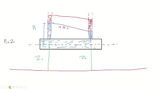
I have to revisit it what is called energy gradient lines or the hydraulic gradient line which is more important when you are solving this pipe network problems.
Detailed Explanation
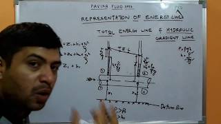
Energy gradient lines represent the total energy available to the fluid flow in a pipe system. They are important for determining how fluids move through pipes, as they indicate changes in energy due to factors such as friction, elevation changes, and flow velocity. When solving pipe network problems, understanding these lines helps engineers predict flow behavior and energy losses, contributing to effective system design.
Examples & Analogies
Think of energy gradient lines like the elevation profile of a hiking trail. Just as the hiking trail's elevation changes affect how easy or hard it is to walk, changes in the energy gradient line affect how easily a fluid can flow through a pipe. If there are steep climbs (energy losses), you would need more energy (pumping) to reach your destination.
Energy Losses in Pipe Systems
Chapter 2 of 4
🔒 Unlock Audio Chapter
Sign up and enroll to access the full audio experience
Chapter Content
So we need to find out how much of energy loss is happening it and what will be the available discharge at different points.
Detailed Explanation
Energy losses in pipe systems occur due to factors like friction, bends, and changes in diameter. Engineers need to calculate these losses to determine how much energy the pump must provide to ensure fluids reach their destinations at required pressures and velocities. Analyzing the available discharge at various points helps in designing a system that meets flow requirements, minimizing energy waste.
Examples & Analogies
Imagine trying to drink from a straw. If the straw is too narrow or has bends, it requires more effort to suck the drink through. Similarly, in a piping system, energy losses can make it harder for fluids to move, requiring more energy to achieve the desired flow rate.
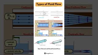
Flow Behavior and Reynolds Numbers
Chapter 3 of 4
🔒 Unlock Audio Chapter
Sign up and enroll to access the full audio experience
Chapter Content
When you talk about turbulence, do not look at the figures like these types of vortex phenomena and all. Always we quantify the turbulence with respect to Reynolds numbers.
Detailed Explanation
The behavior of fluid flow can be classified as laminar or turbulent based on the Reynolds number, which compares inertial forces to viscous forces. A low Reynolds number (less than 2300) indicates laminar flow, characterized by smooth and orderly fluid motion. In contrast, a high Reynolds number (greater than 4000) indicates turbulent flow with chaotic and irregular fluid motion. Understanding these concepts is crucial for predicting how energy gradients affect flow patterns.
Examples & Analogies
Consider a calm river flowing smoothly (laminar), versus a stormy ocean with waves and whirlpools (turbulent). Just as the conditions of the water influence how easily a boat can travel, the fluid flow type affects how energy gradients operate in pipes.
Designing Energy Efficient Systems
Chapter 4 of 4
🔒 Unlock Audio Chapter
Sign up and enroll to access the full audio experience
Chapter Content
All these components of these water supply systems, we need to find out how much of energy loss is happening it and what will be the available discharge at different points.
Detailed Explanation
Designing efficient water supply systems requires engineers to account for energy losses and available discharge at various points. This involves selecting appropriate pipe sizes, materials, and layouts to minimize energy consumption while ensuring that water reaches users effectively. Advanced software can help model these systems, allowing for optimizations based on different scenarios such as seasonal demand changes.
Examples & Analogies
Think of it like planning a road trip. You have to factor in gas efficiency, road conditions, and the type of vehicle you're using to ensure you reach your destination without running out of fuel. Similarly, engineers must design water systems to handle varying demand while minimizing energy consumption.
Key Concepts
-
Energy Gradient Line: Visual representation of energy changes in a pipe system.
-
Bernoulli's Equation: Principle used to analyze fluid flow and energy conservation.
-
Head Loss: The energy lost due to friction and other factors in fluid movement.
Examples & Applications
In designing a water distribution system, engineers must consider the energy gradient line to minimize head loss for optimal efficiency.
When using Bernoulli's equation, the energy gradient lines help in predicting how pressure varies at different points in a pipeline.
Memory Aids
Interactive tools to help you remember key concepts
Rhymes
In a pipe, the energy flows, measure it where the gradient goes.
Stories
Imagine a river flowing down a hill. As it descends, it loses energy, just like we can track water flow through pipes using gradient lines.
Memory Tools
P.E.V. - Potential Energy Visualized through energy gradient lines.
Acronyms
H.E.A.D - Hydraulic Energy And Losses Determined (related to energy gradient and head loss).
Flash Cards
Glossary
- Energy Gradient Line
A line that represents the potential energy of fluid in a pipe system, crucial for analyzing energy losses.
- Hydraulic Gradient Line
A specific type of energy gradient line that indicates the potential energy head of a fluid in relation to the elevation of the system.
- Bernoulli’s Equation
A principle that describes the conservation of energy in fluid flow, relating pressure, velocity, and elevation.
- Head Loss
The loss of energy or pressure in a fluid as it moves through a system, often due to friction.
- Friction Factor
A dimensionless number used to calculate the resistance to flow in a pipe, influencing head loss.
Reference links
Supplementary resources to enhance your learning experience.