
Energy Gradient and Hydraulic Gradient Lines
Enroll to start learning
You’ve not yet enrolled in this course. Please enroll for free to listen to audio lessons, classroom podcasts and take practice test.
Interactive Audio Lesson
Listen to a student-teacher conversation explaining the topic in a relatable way.
Introduction to Gradient Lines
🔒 Unlock Audio Lesson
Sign up and enroll to listen to this audio lesson

Today, we will learn about energy and hydraulic gradient lines. Can anyone tell me why these lines are important in fluid mechanics?

They help us understand how energy is conserved in fluid flow, right?
Exactly! The energy gradient line shows the total energy of the fluid, while the hydraulic gradient line reflects potential energy changes. Remember this with the acronym 'EHP' - Energy is represented as Hydraulic Potential.

How do we sketch these lines?
Great question! You start from the reservoir and plot both lines based on velocity and elevation data. This reveals where energy is lost or gained.
Sketching Gradient Lines
🔒 Unlock Audio Lesson
Sign up and enroll to listen to this audio lesson

Let's look at a diagram of a pumping system. Who can guide me on sketching the energy and hydraulic gradient lines?

First, we'll mark the total energy line, and then the hydraulic gradients will show how much pressure head is available.
That's it! The distance between these lines helps us identify velocity heads. Why is this significant?
It helps in understanding where energy losses occur during flow.
Exactly! The sketch then becomes a tool to analyze flow efficiency.
Historical Experiments and Their Impact
🔒 Unlock Audio Lesson
Sign up and enroll to listen to this audio lesson
Now, let's move on to the historical experiments by Nikuradse. What do you think these experiments taught us?

They showed how roughness impacts flow in pipes?
Yes! His experiments quantified energy losses and velocity distributions. A mnemonic to remember is 'NEL' - Nikuradse Energy Loss.
Why is this relevant now?
Because understanding these relationships helps us in modern design practices for pipes and fluid systems.
Application in Noncircular Conduits
🔒 Unlock Audio Lesson
Sign up and enroll to listen to this audio lesson
Let's discuss applying these concepts to noncircular conduits. How do we define equivalent flow?
By using hydraulic diameters!
Precisely! Hydraulic diameter helps in making correlations similar to circular pipes. This is important because many systems are not circular.
Can you give us an example?
Sure! If we have a rectangular channel, we must calculate the wetted perimeter and area to derive the hydraulic diameter.
Major and Minor Losses in Flow
🔒 Unlock Audio Lesson
Sign up and enroll to listen to this audio lesson
Let's explore major and minor losses in flow. What are they?
Major losses occur due to friction in long pipes, while minor losses happen at bends and fittings.
Excellent! Can anyone explain how we can represent these in a hydraulic gradient line?
They would be reflected as drops in the hydraulic gradient line.
Exactly! Recognizing these losses is crucial for effective system design.
Introduction & Overview
Read summaries of the section's main ideas at different levels of detail.
Quick Overview
Standard
The section outlines the importance of energy and hydraulic gradient lines in understanding fluid flow through pipes, including how to visualize these lines, their relationship to velocity and energy heads, and the implications for designing a pump system. It also introduces historical experiments that contributed to our understanding of these principles.
Detailed
The section focuses on the terms 'Energy Gradient Line' and 'Hydraulic Gradient Line', which are critical in fluid mechanics for analyzing flow systems. The energy gradient line represents the total mechanical energy of the fluid, while the hydraulic gradient line indicates the potential energy due to pressure and elevation in the system. The differences between these lines illustrate velocity heads and energy losses in pipe flow, emphasizing the necessity to sketch these lines for accurate flow analysis. Historical data, such as the experiments conducted by Nikuradse, showcase how roughness in pipes affects flow characteristics and helps define friction factors vital for modern applications. By applying these concepts to noncircular conduits and analyzing major and minor losses, students gain a comprehensive understanding of fluid behavior in varied flow scenarios.
Youtube Videos
![Hydraulic and Energy Grade Line ? with animation [ HGL and EGL ]](https://img.youtube.com/vi/moI4DQNirAw/mqdefault.jpg)

Audio Book
Dive deep into the subject with an immersive audiobook experience.
Understanding Energy and Hydraulic Gradient Lines
Chapter 1 of 4
🔒 Unlock Audio Chapter
Sign up and enroll to access the full audio experience
Chapter Content
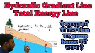
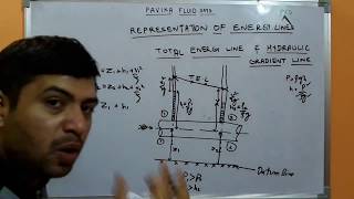
Whenever you have any pipe flow components, like pumping systems or reservoirs, please draw energy gradient lines and hydraulic gradient lines. Those two lines will indicate where energy loss is happening and where energy gain is occurring.
Detailed Explanation
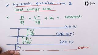
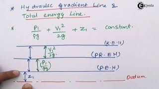
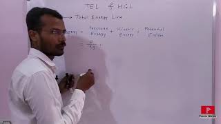
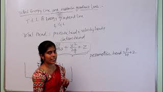
In fluid mechanics, energy gradient lines and hydraulic gradient lines are two essential tools used to analyze fluid flow in pipes. The energy gradient line represents the total energy per unit weight of fluid, which includes potential energy (height), pressure energy, and kinetic energy (velocity). The hydraulic gradient line, on the other hand, specifically shows the pressure energy and potential energy relative to a datum level. By plotting these lines, engineers can visualize where energy is lost (e.g., due to friction) and where energy is gained (e.g., from a pump). A higher energy gradient indicates that the flow has more energy, whereas a downward slope in these lines indicates energy losses.
Examples & Analogies
Think of a water slide in an amusement park. At the top of the slide, there’s maximum potential energy, which translates to high energy gradient. As you slide down, the energy is converted into kinetic energy, and by the time you reach the bottom, the energy gradient decreases. Similarly, in pipe flows, understanding these energy lines helps engineers design systems better to ensure the flow remains efficient and productive.
Components of Energy and Hydraulic Gradient Lines
Chapter 2 of 4
🔒 Unlock Audio Chapter
Sign up and enroll to access the full audio experience
Chapter Content
For example, when discussing a pump, the resistance from the pump provides extra energy to the fluid flow through the pipe systems. This is the reason to draw the energy gradient and hydraulic gradient lines.
Detailed Explanation
Pumps add energy to the fluid to overcome resistance that occurs when fluids flow through pipes. This extra energy is essential for maintaining flow, especially against gravity or friction. By drawing energy and hydraulic gradient lines, we can visually represent this addition of energy. As fluid moves past a pump, the energy gradient line rises, reflecting the increase in energy supplied by the pump, while the hydraulic gradient line may also rise, depending on the pressure head imparted by the pump.
Examples & Analogies
Imagine you're pushing a boulder up a hill. By pushing (similar to what a pump does by adding energy), you provide kinetic energy that helps move the boulder. As it rolls up the hill, it climbs higher in potential energy (reflected in the energy gradient). The process of moving that boulder uphill mirrors how pumps work in a pipe system, adding energy to move fluids where needed.
Major and Minor Losses in Pipe Flow
Chapter 3 of 4
🔒 Unlock Audio Chapter
Sign up and enroll to access the full audio experience
Chapter Content
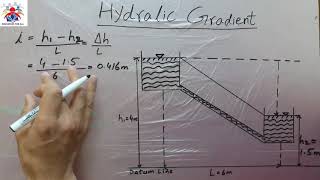
Any datum can have a potential head, pressure head, and velocity head. The hydraulic gradient line drops due to the loss of potential energy along the pipe, which is termed major losses. Bends and entry/exit points cause what we refer to as minor losses.
Detailed Explanation
In pipe flows, energy is lost due to friction (major losses) and changes in flow direction or speed (minor losses). Major losses are often calculated using formulas that account for the entire length of the pipe and its internal roughness. Minor losses are associated with fittings, such as bends, valves, and junctions. The hydraulic gradient line helps us visualize these losses: as fluid travels through the system, the line drops, showing where energy losses occur.
Examples & Analogies
Consider a water hose that bends sharply at some point. When water flows through a straight section, it flows smoothly, but when it hits the bend, there’s a slowdown or energy loss…it’s like trying to run fast while making a sharp turn. To manage these losses effectively, engineers must consider both the straight paths (major losses) and the bends (minor losses) to ensure fluid flows steadily.
Sketching Energy and Hydraulic Gradient Lines
Chapter 4 of 4
🔒 Unlock Audio Chapter
Sign up and enroll to access the full audio experience
Chapter Content
Whenever you have a pipe flow problem, sketch approximately the energy gradient line and the hydraulic gradient line. This helps in understanding how the flow occurs and where energy losses are happening.
Detailed Explanation
Sketching these lines is a fundamental practice in fluid mechanics as it helps engineers visualize the relationship between energy levels throughout the pipe system. By drawing these lines, they can identify areas with significant energy loss or points where energy is added to the system, facilitating better design and troubleshooting.
Examples & Analogies
Think of drawing a map for a journey. Each important point where you either gain or lose altitude (like heads for mountains or valleys) can help you strategize your route better. The energy and hydraulic gradient lines on your map serve a similar function in fluid flow behavior.
Key Concepts
-
Energy Gradient: Represents total mechanical energy in a system.
-
Hydraulic Gradient: Indicates potential energy in fluid due to pressure.
-
Velocity Head: Equivalent height representing kinetic energy.
-
Hydraulic Diameter: A measure used for non-circular conduits based on area and wetted perimeter.
-
Major and Minor Losses: Considerations for energy losses in piping systems.
Examples & Applications
In a simple pipe flow system with a pump, the energy gradient line can be drawn to show increased energy from the pump, whereas the hydraulic gradient line reveals pressure changes.
In a rectangular duct, the hydraulic diameter must be calculated considering the wetted perimeter to accurately predict flow characteristics.
Memory Aids
Interactive tools to help you remember key concepts
Rhymes
Energy flows and pressure shows, Together they go where water flows.
Stories
Once upon a time in a pipe, energy and pressure met; Their journey through bends made it complex, yet together they didn’t forget!
Memory Tools
Remember EHP for Energy Hydraulic Potential.
Acronyms
PHL - Pressure Height Loss
relating energy losses in flow.
Flash Cards
Glossary
- Energy Gradient Line
A line representing the total mechanical energy of the fluid in a system.
- Hydraulic Gradient Line
A line that indicates the potential energy due to pressure and elevation in fluid flow.
- Velocity Head
The height equivalent of the kinetic energy of flowing fluid.
- Hydraulic Diameter
An equivalent diameter used for non-circular conduits determined by the cross-sectional area and wetted perimeter.
- Major Losses
Energy losses occurring primarily due to friction in long pipe runs.
- Minor Losses
Energy losses that occur at fittings, bends, and other discontinuities in piping.
Reference links
Supplementary resources to enhance your learning experience.