
Hydraulic Diameter Definition
Enroll to start learning
You’ve not yet enrolled in this course. Please enroll for free to listen to audio lessons, classroom podcasts and take practice test.
Interactive Audio Lesson
Listen to a student-teacher conversation explaining the topic in a relatable way.
Understanding Hydraulic Diameter
🔒 Unlock Audio Lesson
Sign up and enroll to listen to this audio lesson

Today we'll discuss hydraulic diameter, a crucial concept when evaluating fluid flow in noncircular conduits. Can anyone tell me why we need a different measurement for noncircular shapes?

Because circular pipes behave differently from noncircular ones, right?
Exactly! The hydraulic diameter helps us predict how fluids will behave in different shapes. It is defined as `D_h = 4 * A / P_w`, where `A` is the area and `P_w` is the wetted perimeter. Remember, this formula allows us to use familiar circular flow equations for complex shapes!

So, if the wetted perimeter changes, does the hydraulic diameter change too?
Yes! That's a great observation. If the wetted perimeter increases, the hydraulic diameter decreases, affecting flow characteristics. This relationship is key in fluid dynamics.

Can you clarify how we calculate the area for a noncircular shape?
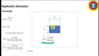
Sure! For example, for a rectangular conduit, the area `A` would be simply length times width. The calculation is straightforward but varies with shape. Make sure to familiarize yourselves with these formulas!
To summarize, hydraulic diameter helps translate circular flow equations for various shapes by factoring in both area and wetted perimeter. Keep this in mind as we delve deeper!
Applications of Hydraulic Diameter
🔒 Unlock Audio Lesson
Sign up and enroll to listen to this audio lesson

Now that we understand hydraulic diameter, let's explore its applications. Can anyone mention where this concept might be essential?

I think it could be useful in pipeline designs for sewage systems or water treatment plants.
Absolutely! Engineers use hydraulic diameter to determine flow rates and pump requirements in these systems. It affects everything from sizing pipes to estimating energy loss due to friction.
So, if the hydraulic diameter is incorrect, it could lead to system failures?
Right again! An inaccurate diameter could lead to insufficient flow or excessive pressure buildup, causing significant operational issues. Always ensure precise measurements!
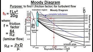
Are there formulas or charts, like Moody's chart, that help engineers reference hydraulic diameters?
Yes, Moody's chart can give insights into friction factors, helping to relate hydraulic diameter to flow conditions in circular pipes. Similar principles apply when converting those insights into noncircular scenarios.
Once again, hydraulic diameter is integral to many hydraulic calculations related to noncircular conduits. Always factor it into your fluid analyses!
Further Concepts and Considerations
🔒 Unlock Audio Lesson
Sign up and enroll to listen to this audio lesson
To wrap up our discussion, let's consider more complex flow scenarios. Can anyone think of an example where hydraulic diameter might vary?
How about a pipe partially filled with liquid?
Great point! In such cases, we only consider the wetted perimeter of the liquid. The hydraulic diameter must be recalculated, affecting flow resistance.
Does that mean the efficiency of pipe flow could drastically change due to changes in hydraulic diameter?
Indeed. A smaller hydraulic diameter means higher resistance, which directly impacts flow efficiency, pump selection, and energy costs! Always measure and calculate accurately.
Last question, how does the geometry of the conduit impact the flow profile?
Excellent question. Noncircular conduits often create uneven velocity distributions and varying shear stresses, compared to circular ones. Understanding these intricacies is vital for accurate modeling.
In summary, whether analyzing flow rates in partially filled conduits or assessing the impact of geometric changes, hydraulic diameter remains a fundamental aspect of fluid mechanics. Always remember its significance!
Introduction & Overview
Read summaries of the section's main ideas at different levels of detail.
Quick Overview
Standard
The section elaborates on the concept of hydraulic diameter as a critical measure in fluid flow through noncircular conduits. It discusses how hydraulic diameters are derived from the flow area and wetted perimeter and how they compare to geometric diameters in circular pipes.
Detailed
Detailed Summary
The hydraulic diameter is an essential concept when dealing with fluid flow in noncircular conduits. It is defined as the ratio of four times the flow area to the wetted perimeter. For circular pipes full of liquid, the hydraulic diameter equals the geometric diameter. In situations where the conduit is not circular, like rectangular or triangular shapes, the calculation of hydraulic diameter involves specific formulas to account for the wetted perimeter and flow area.
Key Points Covered:
- Definition of Hydraulic Diameter: The equation for calculating hydraulic diameter (
D_h = 4 * A / P_w) whereAis the flow area, andP_wis the wetted perimeter. - Significance: Hydraulic diameter aids in understanding flow characteristics, such as velocity distribution and shear stress.
- Application: The hydraulic diameter concept is crucial when analyzing noncircular conduits like annular, rectangular, or triangular pipes and relevant to predicting flow behaviors in various engineering applications.
Youtube Videos
![[HYDRAULIC #2] Hydraulic Diameter and it application and comparison with Geometric Diameter](https://img.youtube.com/vi/m7dNIELIHps/mqdefault.jpg)


Audio Book
Dive deep into the subject with an immersive audiobook experience.
Introduction to Hydraulic Diameter
Chapter 1 of 5
🔒 Unlock Audio Chapter
Sign up and enroll to access the full audio experience
Chapter Content
Now coming back to the noncircular conduit like you may have a conditions where you have only flow through this ones okay. That is called circular annulus diameter. \( D \) is the diameter and the flow through these ones.
Detailed Explanation
In fluid mechanics, the hydraulic diameter is a way to generalize the concept of diameter for non-circular conduits. When fluid flows through a pipe that is not perfectly circular, such as in a situation where it flows through a circular annulus (the space between two concentric circles), we still need a way to define an 'equivalent' diameter that helps us calculate other properties of the flow, like velocity and pressure loss.
Examples & Analogies
Imagine a narrow conduit, similar to a straw, where the cross-section is shaped like an arch rather than a circle. Just as we can calculate how much liquid can flow through a straw by referencing its diameter, we can do the same with this arch shape by using the hydraulic diameter, which allows us to use the familiar concepts from circular pipes on these more complex shapes.
Calculating Hydraulic Diameter
Chapter 2 of 5
🔒 Unlock Audio Chapter
Sign up and enroll to access the full audio experience
Chapter Content
The hydraulic diameter is defined as \( D_h = \frac{4A}{P} \), which is a function of area and wetted perimeter. If I have the flow pipes, it is going through whole, so that way the total perimeter I can consider as wetted perimeter.
Detailed Explanation
The hydraulic diameter \( D_h \) is calculated using the formula \( D_h = \frac{4A}{P} \), where \( A \) represents the cross-sectional area of the flow and \( P \) denotes the wetted perimeter of the conduit. The wetted perimeter is the part of the pipe's boundary that is in contact with the fluid. For example, if the pipe is completely filled, we consider the entire perimeter. However, if the fluid only partially fills the pipe, we only consider the wetted portion.
Examples & Analogies
Think of this like measuring a swimming pool. The area of the water surface is analogous to the cross-sectional area, while the sides of the pool that touch the water are like the wetted perimeter. If we want to describe how well water flows in and out of the pool, we would use these two measurements to find an average or equivalent shape that helps us understand the flow.
Hydraulic Diameter in Circular Pipes
Chapter 3 of 5
🔒 Unlock Audio Chapter
Sign up and enroll to access the full audio experience
Chapter Content
If we substitute if the \( D \) is a diameters and the perimeter for the whole flow of these pipe systems, you will get it hydraulic diameter in a circular pipe when it contains full of water.
Detailed Explanation
When dealing with regular circular pipes, the hydraulic diameter simplifies greatly. If the pipe is entirely filled with liquid, the hydraulic diameter equals the physical diameter of the pipe. The formula simplifies to a form where the area and perimeter correlate directly since all the sides of the circular pipe contribute to the flow characteristics equally.
Examples & Analogies
Imagine a standard drinking straw. If you fill the straw completely with juice, the hydraulic diameter is simply the diameter of that straw because every part of its inner surface is being utilized by the juice. In cases like these, calculations for flow become much easier.
Hydraulic Diameter for Non-Circular Shapes
Chapter 4 of 5
🔒 Unlock Audio Chapter
Sign up and enroll to access the full audio experience
Chapter Content
Now come back to the noncircular conduit like you may have a conditions where you have a only flow through this ones okay. That is called circular annulus diameter.
Detailed Explanation
Hydraulic diameter is especially useful for non-circular shapes. For cases where the conduit is, for example, an annulus (the space between two tubes), one must calculate the area of the flow and the wetted perimeter specifically for that shape. This serves to determine the hydraulic diameter, which can be significantly different from the simple geometric diameter used in circular pipes due to varying dimensions.
Examples & Analogies
Consider a double-walled tubing where fluid flows through the inner tube. Here, the fluid is in contact with the inner surface, and the hydraulic diameter provides a way to capture this complex geometry into a manageable calculation, similar to how we would calculate the effective cross-section of traffic flowing through a busy highway with multiple lanes.
Visualizing Flow Patterns in Non-Circular Conduits
Chapter 5 of 5
🔒 Unlock Audio Chapter
Sign up and enroll to access the full audio experience
Chapter Content
If you have a triangular flow zone, you will have wall stress maximum at the midpoints of the sides.
Detailed Explanation
When examining non-circular conduits like triangles, the distribution of shear stress varies significantly compared to circular flows. For laminar flow in a triangular channel, the maximum wall shear stress occurs at the midpoints of the triangle's sides, and it's zero at the corners. This behavior significantly impacts flow patterns and energy loss within the conduit.
Examples & Analogies
Picture a triangular water slide. When water flows down the slide, it moves fastest in the middle sections (like at the midpoint of the sides), while at the corners, it slows down or circulates differently. Understanding where the maximum stress and flow happens helps engineers design better water drainage and hydraulic systems.
Key Concepts
-
Hydraulic Diameter: A measure derived from flow area and wetted perimeter.
-
Wetted Perimeter: The perimeter of a conduit in contact with the fluid.
-
Flow Area: The effective cross-section through which fluid moves.
Examples & Applications
When calculating for a rectangular conduit, if the width is 2m and height is 1m, the flow area A would be 2m × 1m = 2m². The wetted perimeter P_w would be 2m + 2m = 4m, leading to a hydraulic diameter of D_h = 4 * 2 / 4 = 2m.
In a circular pipe filled halfway, the wetted perimeter would only be half the circular circumference, affecting the hydraulic diameter and consequently, flow conditions.
Memory Aids
Interactive tools to help you remember key concepts
Rhymes
To find the diameter that helps the flow, use area and perimeter as your guide, now you know!
Stories
Imagine a river winding through different shapes. To understand how water moves, we create a hydraulic diameter, blending area and perimeter like clever architects planning a flow.
Memory Tools
Remember 'H D = A over P' to keep hydraulic diameter clear, you’ll see!
Acronyms
‘HDA’ - Hydraulic diameter = Area / Wetted Perimeter.
Flash Cards
Glossary
- Hydraulic Diameter (D_h)
The measure of diameter used in noncircular conduits calculated as
D_h = 4 * A / P_w, whereAis the flow area andP_wis the wetted perimeter.
- Wetted Perimeter (P_w)
The part of the perimeter of a conduit that is in contact with the flowing liquid.
- Flow Area (A)
The cross-sectional area through which fluid flows, essential for calculating flow rates and hydraulic diameter.
Reference links
Supplementary resources to enhance your learning experience.