
Energy Loss in Pipe Flow
Enroll to start learning
You’ve not yet enrolled in this course. Please enroll for free to listen to audio lessons, classroom podcasts and take practice test.
Interactive Audio Lesson
Listen to a student-teacher conversation explaining the topic in a relatable way.
Introduction to Energy Loss
🔒 Unlock Audio Lesson
Sign up and enroll to listen to this audio lesson

Today, we are going to explore energy loss in pipe flow. Can anyone tell me what factors might lead to energy loss in pipes?

Maybe the friction between the fluid and the pipe walls?
Exactly! Friction is a significant factor. We refer to energy loss due to friction as 'major losses.' Can anyone give me an example of 'minor losses'?

What about energy loss at bends or valves?
Well done! Those are perfect examples of minor losses. Remember, minor losses occur at points of change in flow direction or cross-section.
Hydraulic Diameter in Noncircular Conduits
🔒 Unlock Audio Lesson
Sign up and enroll to listen to this audio lesson

Let's shift our focus to noncircular conduits. Why do you think we need to calculate a 'hydraulic diameter' for these?

To simplify calculations for different shapes?
That's correct! The hydraulic diameter helps determine how fluid behaves in those conduits as if they were circular. Can anyone tell me the formula for hydraulic diameter?

It's 4 times the area divided by the wetted perimeter.
Excellent! Remember, the wetted perimeter is critical in these calculations.
Historical Experiments and Their Impact
🔒 Unlock Audio Lesson
Sign up and enroll to listen to this audio lesson
Now, let’s talk about a significant milestone in fluid mechanics – the experiments conducted by Nikuradse. What do you think he measured in his studies?
Friction factors and velocity distributions in pipes?
That's right! His work led to the development of the Moody chart. Does anyone know how it helps engineers today?
It helps estimate friction factors for different flows!
Absolutely! It's a tool still utilized in pipeline design today.
Application of Energy Loss Concepts
🔒 Unlock Audio Lesson
Sign up and enroll to listen to this audio lesson
Finally, let’s discuss how to apply these concepts to real-world problems. Who can think of a scenario where energy loss would be critical to calculate?
In designing water distribution systems?
Exactly! Engineers need to ensure that the water pressure remains effective throughout the system by accounting for energy losses. Can you think of tools or methods we can use for these calculations?
Using charts like Moody's or calculating using the Darcy-Weisbach equation?
Perfect! Don't forget that understanding energy losses is key to efficient fluid systems.
Introduction & Overview
Read summaries of the section's main ideas at different levels of detail.
Quick Overview
Standard
Energy losses in pipe flow are crucial to understanding fluid mechanics. This section explores the concepts of major and minor losses, the derivation of hydraulic diameters for noncircular conduits, and historical experiments that shaped modern fluid dynamics principles.
Detailed
Energy Loss in Pipe Flow
In fluid mechanics, understanding energy loss in pipe flow is crucial for various applications. This section focuses on how energy loss occurs due to friction and other factors when fluid flows through pipes. Major losses are primarily related to friction when fluid flows in straight sections of pipes, while minor losses occur at bends, fittings, and other obstructions.
An essential part of managing these losses involves the hydraulic diameter, particularly in noncircular conduits where traditional calculations using circular geometry do not apply. The section also highlights significant historical experiments, particularly by Nikuradse, which quantified these phenomena and introduced concepts like the Moody chart for estimating friction factors. These empirical relationships are vital for engineers designing efficient fluid systems today.
Youtube Videos


![[MAE 242] Pipe flow with major and minor head losses](https://img.youtube.com/vi/WH1fn6dMYiw/mqdefault.jpg)


Audio Book
Dive deep into the subject with an immersive audiobook experience.
Energy Gradient and Hydraulic Gradient Lines
Chapter 1 of 5
🔒 Unlock Audio Chapter
Sign up and enroll to access the full audio experience
Chapter Content
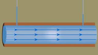
Whenever you have any pipe flow components, such as pumping systems and reservoirs, please draw the energy gradient line and the hydraulic gradient line. These lines will indicate where energy loss is happening and where energy is gaining. For example, when discussing a pump, the resistance it provides adds extra energy to the fluid as it flows through the pipe systems. This is why it's important to draw these lines to visualize energy changes in the system.
Detailed Explanation
In pipe flow systems, the energy gradient line represents the total energy available to the fluid, while the hydraulic gradient line represents the energy due to pressure head and elevation. Energy can be gained or lost at different points in the system, which is critical to understanding fluid behavior, especially in explaining how pumps add energy and where losses occur due to friction or bends in the pipe.
Examples & Analogies
Imagine you are at a water park. The energy gradient is similar to how high you are on the slides, which helps you gain speed as you go down. The hydraulic gradient could be thought of as the water pressure pushing you down the slide. When you hit a bend, it’s like going over a bump that slows you down, similar to energy loss in the pipes.
Major and Minor Losses
Chapter 2 of 5
🔒 Unlock Audio Chapter
Sign up and enroll to access the full audio experience
Chapter Content
There are major and minor losses in pipe flow. Major losses occur due to friction within the pipe over long distances, while minor losses are usually due to fittings, bends, transitions, or other disturbances. We quantify these losses through mathematical relationships, and it’s essential to understand how they influence the overall energy loss in a pipe system.
Detailed Explanation
In engineering, we categorize energy losses in pipe flow into major and minor losses. Major losses are primarily due to the pipe's internal friction, which increases as the length of the pipe increases or when the fluid's velocity increases. On the other hand, minor losses come from components such as valves and bends that introduce turbulence and additional friction. Understanding both types of losses is vital for designing efficient pipe systems.
Examples & Analogies
Think of a long garden hose where the brand of your hose represents the pipe material. A thinner hose (more friction) will slow down the water flowing out of it (major loss), while the spray nozzle you're using (like a bend) also creates additional resistance (minor loss) every time you change the way water flows out.
Nikuradse's Experiments on Turbulent Flow
Chapter 3 of 5
🔒 Unlock Audio Chapter
Sign up and enroll to access the full audio experience
Chapter Content
In the 1930s, Professor Nikuradse conducted classic experiments on pipe flow that quantified energy loss and velocity distributions in turbulent flow conditions. Using pipes lined with different roughness levels, he established relationships between flow characteristics, roughness, and energy loss. His work laid the groundwork for understanding friction factors in turbulent flow.
Detailed Explanation
Nikuradse's experiments involved using different roughness elements in pipes to see how they affected fluid flow and energy loss. This groundbreaking research allowed for the development of the Moody chart, which engineers rely on today to determine friction factors for various flow scenarios. Understanding how roughness affects flow characteristics is essential for accurate engineering calculations.
Examples & Analogies
Imagine running a race on different surfaces – sand, grass, and a track. Each surface has a different level of friction, which affects your speed. Nikuradse's experiments are like testing runners on these different surfaces to see how they perform and how much energy they lose due to friction.
Hydraulic Diameter in Noncircular Conduits
Chapter 4 of 5
🔒 Unlock Audio Chapter
Sign up and enroll to access the full audio experience
Chapter Content
For noncircular conduits, we need to define an equivalent flow parameter called hydraulic diameter. This is calculated using the area and wetted perimeter of the flow cross-section. This concept allows for the comparison of noncircular flow to traditional circular pipe flow.
Detailed Explanation
Hydraulic diameter helps engineers analyze the flow in non-standard pipe shapes by providing an equivalent measurement. The hydraulic diameter is calculated by taking four times the cross-sectional area divided by the wetted perimeter. This allows for a more straightforward analysis similar to that of circular pipes, making it essential for fluid dynamics in various applications.
Examples & Analogies
Think of drinking from a straw. A regular straw is circular, while a flat one might be more rectangular. To compare their flow efficiency, we calculate the hydraulic diameter to understand how well they let liquid flow through, just as we would in designing pipes of different shapes.
Velocity Profile in Turbulent Flow
Chapter 5 of 5
🔒 Unlock Audio Chapter
Sign up and enroll to access the full audio experience
Chapter Content
In turbulent flow, the velocity distribution near the pipe wall is complex and differs significantly from laminar flow. Research by Nikuradse indicates that the velocity profile flattens with increasing Reynolds numbers up to three million, leading to a change in how we understand shear stress and energy losses.
Detailed Explanation
The velocity profile in turbulent flow differs because the fluid particles engage in chaotic movements, compared to the smooth and orderly flow seen in laminar conditions. As the flow becomes more turbulent, the velocity at the center maintains higher speeds, while the transition zones close to the wall slow down. This results in complicated interactions regarding shear stress, which directly impacts energy loss calculations.
Examples & Analogies
Consider a busy highway at rush hour compared to a quiet suburban road. On the highway (turbulent flow), most cars (fluid particles) are moving quickly, but near the edges (the walls), some cars are slower due to merging lanes, just like how the velocity profile is affected near pipe walls. Understanding these dynamics helps manage traffic flow, similar to managing fluid flow in pipes.
Key Concepts
-
Energy Loss: The reduction of energy due to friction and turbulence in fluid flows.
-
Major Losses: Primarily due to the friction in long pipe segments.
-
Minor Losses: Occur at bends, fittings, and other obstructions.
-
Hydraulic Diameter: A measurement useful for calculating flow characteristics in noncircular conduits.
-
Moody Chart: A tool used to estimate the friction factor in fluid flow.
Examples & Applications
In a water distribution system, calculating the energy loss due to friction is critical to ensuring adequate pressure at the tap.
When designing irrigation systems, understanding minor losses due to bends and valves helps optimize water flow.
Memory Aids
Interactive tools to help you remember key concepts
Rhymes
In pipes long and short, energy loss is a sport; watch for friction, bends—a lesson essential, think of flows that's consequential.
Stories
Imagine a water flow festival where the pipes are roads. Friction is a heavy traffic jam that slows down delivery time, preventing fast access to the grand feast at the end.
Memory Tools
To remember major and minor losses, think: 'Friction For Major, Bends For Minor.'
Acronyms
For energy loss in pipes, think
MEL (Major Energy loss due to Friction
Minor Energy loss at bends).
Flash Cards
Glossary
- Energy Loss
The loss of energy that occurs as fluid flows through pipes due to factors like friction and turbulence.
- Major Losses
Energy losses primarily due to friction over long pipe lengths.
- Minor Losses
Energy losses that occur at fittings, bends, valves, and other disruptions in flow.
- Hydraulic Diameter
A calculation used for noncircular conduits to estimate flow characteristics.
- Moody Chart
A graphical representation used to estimate the friction factor in pipe flow based on Reynolds number and relative roughness.
Reference links
Supplementary resources to enhance your learning experience.