
Major and Minor Losses
Enroll to start learning
You’ve not yet enrolled in this course. Please enroll for free to listen to audio lessons, classroom podcasts and take practice test.
Interactive Audio Lesson
Listen to a student-teacher conversation explaining the topic in a relatable way.
Introduction to Major and Minor Losses
🔒 Unlock Audio Lesson
Sign up and enroll to listen to this audio lesson

Today, we are discussing major and minor losses in fluid mechanics. Major losses are primarily due to friction in the lengths of pipes, while minor losses occur due to fittings and other flow disturbances. Can anyone explain why understanding these losses is crucial in engineering?

It's important because we want to design systems that minimize energy loss and optimize flow efficiency.

And to ensure that systems can handle the expected flow rates without excessive pressure drops!
Exactly! The impact of these losses can be measured using energy and hydraulic gradient lines. Can anyone differentiate between major and minor losses with an example?

A major loss can occur when water flows through a long section of pipe, while a minor loss happens at a bend or valve.
Great explanation! Remember: major losses relate to the length of the pipe, while minor losses relate to flow disruptions. This distinction will help us in future designs.
Quantifying Major Losses
🔒 Unlock Audio Lesson
Sign up and enroll to listen to this audio lesson

Now let's quantify major losses. Major losses can be calculated using empirical formulas, often involving friction factors from the Moody chart. Does anyone know what factors influence these losses?

The pipe diameter, flow velocity, and the roughness of the pipe surface are crucial!
Correct! The Reynolds number also plays a significant role in determining the flow regime. Can someone explain how we use the Moody chart for these calculations?
The Moody chart gives us the friction factor based on the Reynolds number and relative roughness of the pipe.
Well said! Keep this process in mind, as it forms the foundation of calculating losses in pipe systems.
Understanding Minor Losses
🔒 Unlock Audio Lesson
Sign up and enroll to listen to this audio lesson
Moving on to minor losses—how are they calculated? They are generally expressed as a fraction of the velocity head. Can anyone explain further?
Yes! We use loss coefficients for different fittings, which represent how much energy is lost compared to a straight section of pipe.
Right! For example, a sharp elbow has a higher coefficient than a gradual bend.
Exactly! It's vital to be aware of these coefficients. They help us determine how to design efficient systems.
Practical Applications
🔒 Unlock Audio Lesson
Sign up and enroll to listen to this audio lesson
Let's discuss the practical implications of what we learned. How would you apply these concepts in real-world engineering?
We can analyze existing systems to find where we can reduce losses, like optimizing the layout of pipes!
And also, choosing materials that minimize roughness could help reduce major losses.
Great thoughts! Effective application of these principles is crucial in designing efficient and cost-effective fluid systems in various industries.
Introduction & Overview
Read summaries of the section's main ideas at different levels of detail.
Quick Overview
Standard
In this section, we explore the concepts of major and minor losses that occur in fluid systems, particularly in pipe flows. Major losses are related to the length and diameter of pipes, while minor losses arise from fittings, bends, and other flow obstructions. Theoretical foundations and empirical relationships, including those from the Moody chart, are discussed alongside practical implications for engineering applications.
Detailed
Major and Minor Losses
This section provides an in-depth exploration of major and minor losses in fluid mechanics, particularly in the context of flow through pipes and conduits. Major losses are primarily attributed to friction along the length of the pipe, which depends on the type and roughness of the pipe material, as well as the flow velocity and the Reynolds number. The concept of minor losses, on the other hand, refers to energy loss caused by fittings, bends, valves, and other elements disrupting the flow, often represented as a fraction of the dynamic pressure.
The relationship between these losses can be quantified using the energy gradient and hydraulic gradient lines, which help visualize where the energy is lost or gained in the flow system. The section highlights key empirical findings, particularly those from Nikuradse's experiments, which established relationships instrumental for understanding flow resistance in both circular and non-circular conduits. The discussion extends to hydraulic diameters, especially in non-circular conduits, where the effective area and wetted perimeter determine flow characteristics. By applying this knowledge, engineers can better design piping systems to minimize losses and improve efficiency.
Youtube Videos


![[MAE 242] Pipe flow with major and minor head losses](https://img.youtube.com/vi/WH1fn6dMYiw/mqdefault.jpg)


Audio Book
Dive deep into the subject with an immersive audiobook experience.
Understanding Major and Minor Losses
Chapter 1 of 4
🔒 Unlock Audio Chapter
Sign up and enroll to access the full audio experience
Chapter Content
Whenever you have any pipe flow components, like pumping systems and reservoirs, please draw the energy gradient line and the hydraulic gradient line. These two lines will indicate where energy loss is happening and where energy is gained.
Detailed Explanation
In fluid mechanics, when fluid flows through pipes, we notice energy losses due to friction and other factors. To help visualize this, we draw two important lines: the energy gradient line and the hydraulic gradient line. The energy gradient line represents the total energy of the fluid at different points along the pipe, while the hydraulic gradient line shows the pressure head of the fluid. The difference between these lines indicates where energy is lost (major losses) and where energy is added (through pumps, for example).
Examples & Analogies
Think of a water slide at a theme park. As water flows down the slide, it loses potential energy (height) and kinetic energy (speed) due to friction. If we draw the slide's energy levels at various points, we can see where it’s losing energy to friction (like major losses) and where the water is speeding up (like minor losses when the slide curves).
Classification of Energy Losses
Chapter 2 of 4
🔒 Unlock Audio Chapter
Sign up and enroll to access the full audio experience
Chapter Content
As you draw the energy gradient line and the hydraulic gradient line, you can identify the flow processes, whether the major losses, minor losses, or added energy to the system.
Detailed Explanation
Energy losses in pipe flow can be categorized into two types: major and minor losses. Major losses are primarily due to the frictional resistance within the pipe, while minor losses occur due to fittings, bends, and other obstructions. By analyzing the energy gradient and hydraulic gradient lines, we can pinpoint where these losses occur and understand their impact on the overall fluid flow.
Examples & Analogies
Imagine driving on a highway. The major losses are like the drag your car experiences due to friction with the road. Minor losses are akin to the slowdowns you feel when navigating sharp turns or taking exits. By recognizing these elements, you can better understand the overall dynamics of your drive (or fluid flow).
Experiments in Fluid Mechanics
Chapter 3 of 4
🔒 Unlock Audio Chapter
Sign up and enroll to access the full audio experience
Chapter Content
In the 1930s, an experiment was conducted by Nikuradse with rough pipes that has defined major and minor losses in turbulent flow. They established relationships between friction factors and Reynolds numbers, leading to the Moody chart, a critical tool in pipe flow design.
Detailed Explanation
In the 1930s, professor Nikuradse conducted significant experiments that helped define how major and minor losses affect fluid flow in pipes. By using pipes with controlled wall roughness, he was able to analyze how energy losses changed with different flow conditions. He discovered that, as the roughness of the pipe's interior surface increased, the friction factor also increased. This led to the creation of the Moody chart, a graphical representation that correlates friction factor, Reynolds number, and relative roughness, which engineers use to predict energy losses in fluid systems.
Examples & Analogies
Consider a water pipe as a road for cars. A smooth asphalt road allows cars to drive efficiently, while a bumpy gravel road slows them down. Similarly, Nikuradse’s experiments show that a smoother pipe reduces energy loss (like a good road), while a rougher pipe increases it (like a rough road). The Moody chart helps engineers choose the right 'road' (or pipe) for different situations.
Calculating Hydraulic Diameter
Chapter 4 of 4
🔒 Unlock Audio Chapter
Sign up and enroll to access the full audio experience
Chapter Content
When dealing with noncircular conduits, we introduce the concept of hydraulic diameter, which is defined as a function of area and wetted perimeter. This helps to equate noncircular pipe flows to circular pipe flows.
Detailed Explanation
In systems where fluid flows through shapes other than circular pipes (like rectangular or triangular ducts), we need a way to calculate the effective diameter that would give us the same hydraulic characteristics as a circle. This is where the hydraulic diameter comes in, defined by the formula: hydraulic diameter = 4 × (cross-sectional area) / (wetted perimeter). Understanding this concept allows engineers to estimate flow behavior and energy losses even in nontraditional pipe shapes.
Examples & Analogies
Think of hydraulic diameter like sizing a dress. Just as a dress is tailored to fit by adjusting its width and length to suit an individual's body shape, hydraulic diameter adjusts the dimensions of a noncircular pipe so that it behaves similarly to a circular pipe for fluid flow. It ensures that we can still predict how fluids will flow through various shapes even if they aren’t round.
Key Concepts
-
Major Losses: Losses attributed to friction along pipe lengths.
-
Minor Losses: Losses due to fittings and obstructions in flow.
-
Moody Chart: A graph that provides friction factors for various pipe conditions.
-
Hydraulic Diameter: An equivalent diameter for non-circular conduits.
Examples & Applications
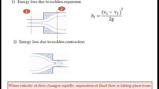
A straight section of pipe exhibiting major losses can be analyzed using the Darcy-Weisbach equation to quantify these losses.
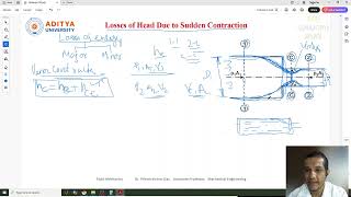
Minor losses can be calculated using coefficients for specific fittings, such as a valve or elbow, applied to the dynamic pressure conditions.
Memory Aids
Interactive tools to help you remember key concepts
Rhymes
In pipes, energy we might lose, Major from friction, minor from the bends we choose.
Stories
Imagine a water flow party: when go through straight paths, there's little resistance (major loss), but whenever it hits the furniture (fittings), energy splashes around (minor loss).
Memory Tools
Remember 'FME' for fluid losses: 'Friction for Major, Minor for Fittings and Edges'.
Acronyms
Use JAW (Just Add Water) to remember
for Junctions (minor losses)
for Area (flow area)
for Wet perimeters (hydraulic diameter).
Flash Cards
Glossary
- Major Losses
Energy losses in fluid flow primarily due to friction along the length of a pipe.
- Minor Losses
Energy losses in fluid flow caused by fittings, bends, and other disturbances.
- Moody Chart
A graphical representation of the friction factor, dependent on the Reynolds number and relative roughness of the pipe.
- Hydraulic Diameter
A measure used to characterize noncircular conduits, related to the flow area and wetted perimeter.
Reference links
Supplementary resources to enhance your learning experience.