
Noncircular Conduits
Enroll to start learning
You’ve not yet enrolled in this course. Please enroll for free to listen to audio lessons, classroom podcasts and take practice test.
Interactive Audio Lesson
Listen to a student-teacher conversation explaining the topic in a relatable way.
Introduction to Noncircular Conduits
🔒 Unlock Audio Lesson
Sign up and enroll to listen to this audio lesson

Today we are discussing noncircular conduits and how they differ from circular ones. Noncircular conduits require us to define what we call a hydraulic diameter, which is essential for our calculations.

What exactly is a hydraulic diameter?
Great question! The hydraulic diameter is defined as four times the flow area divided by the wetted perimeter. It helps in understanding the flow characteristics in any sufficiently complex geometry.

So how does the shape of the conduit affect the hydraulic diameter?
The shape directly influences both the flow area and wetted perimeter. For instance, in a rectangular conduit, you'll need the rectangle's width and height to calculate those measurements.

Can you give us an example?
Sure! For a rectangle with width 'b' and height 'h', the hydraulic diameter, Dh, can be calculated as 4Ah/P. Remember, Ah is the area and P is the wetted perimeter, which in this case is '2b + 2h'!
In summary, understanding the hydraulic diameter is crucial for analyzing fluid behavior in noncircular conduits.
Impact of Pipe Roughness
🔒 Unlock Audio Lesson
Sign up and enroll to listen to this audio lesson

Today, let's discuss the impact of pipe roughness on fluid flow, building on the work of Nikuradse, who conducted significant experiments back in the 1930s.
What did Nikuradse find in his experiments?
Nikuradse introduced roughness elements like sand grains in pipes to study their impact on flow. He discovered that as roughness increased, it affected the friction factors and overall energy losses.
And how does that relate to our calculations?
When calculating friction factors for turbulent flow, you can see how roughness interacts with Reynolds numbers. The greater the roughness and flow velocity, the more significant the friction losses will be.

Why is this important for industries like water treatment or sewage management?
Understanding how roughness impacts flow helps engineers design systems that minimize energy losses, ensuring efficiency in processes like water supply and sewage treatment.
To summarize, roughness can significantly influence fluid flow dynamics, which is crucial for practical applications.
Velocity Distribution in Turbulent Flow
🔒 Unlock Audio Lesson
Sign up and enroll to listen to this audio lesson
Let’s explore how velocity distribution behaves under turbulent flow conditions.
How does velocity distribution differ between laminar and turbulent flows?
In laminar flow, velocity is typically parabolic in shape, while in turbulent flow, it becomes flatter – with most flow occurring in the center of the conduit.
What about the role of Reynolds number here?
Great point! The Reynolds number indicates the flow regime. For instance, a Reynolds number below 2000 typically indicates laminar flow, while above 4000 signifies turbulent flow.
How do we express the velocity distribution mathematically?
It's often expressed in non-dimensional forms to relate wall shear stress, hydraulic diameter, and flow conditions, essential for calculations.
In summary, turbulence significantly modifies velocity distribution in fluids, heavily influenced by both fluid and conduit characteristics.
Wall Shear Stress and Its Significance
🔒 Unlock Audio Lesson
Sign up and enroll to listen to this audio lesson
Today we'll discuss wall shear stress, a critical concept when analyzing noncircular conduits.
What is wall shear stress, exactly?
Wall shear stress is the force exerted by the fluid on the walls of the conduit. It's crucial for predicting energy losses in flow.
How do we calculate it?
It can be derived from empirical relationships involving average velocities and hydraulic radius, often expressed through parameters like Reynolds number.
Why is that so important in real-world applications?
By understanding wall shear stress, engineers can design systems that operate efficiently, addressing concerns like energy consumption and flow stability.
In conclusion, recognizing and calculating wall shear stress is vital in fluid mechanics, particularly with noncircular conduits.
Real-World Applications and Implications
🔒 Unlock Audio Lesson
Sign up and enroll to listen to this audio lesson
In our final session, let's discuss how these concepts from today apply to real-world scenarios.
Can you give an example of where noncircular conduits are used?
Certainly! Noncircular conduits are common in sewage systems, where various shapes accommodate different flow characteristics.
What about their application in water treatment?
In designs for water treatment plants, understanding flow characteristics helps minimize sedimentation and optimize chemical dosing.
What key takeaway should we remember about these conduits?
Understanding the impact of conduit shape on flow helps engineers make informed decisions to create efficient, robust systems.
In summary, applying fluid mechanics principles to real-world situations allows us to improve infrastructure efficiency and effectiveness.
Introduction & Overview
Read summaries of the section's main ideas at different levels of detail.
Quick Overview
Standard
This section elaborates on the behavior of fluid flow in noncircular conduits, emphasizing the calculation of hydraulic diameters and the implications of roughness on velocity distribution and wall shear stress, utilizing empirical studies such as Nikuradse’s experiments as a foundation for understanding turbulence in pipes.
Detailed
In this section, we delve into the dynamics of fluid flow in noncircular conduits. Noncircular conduits require the definition of hydraulic diameter, which is computed as a function of flow area and wetted perimeter. The section discusses various geometries of conduits including rectangular and triangular shapes, providing formulas to calculate hydraulic diameters for each case. We also explore the impact of pipe roughness on flow characteristics, especially through the seminal experiments conducted by Nikuradse which established fundamental relationships between flow regimes, roughness, and wall shear stress. Understanding these relationships is crucial for predictive modeling in engineering applications ranging from water supply to sewage treatment. The section also emphasizes the significance of calculating velocity distributions in turbulent flow, establishing connections between Reynolds number, friction factor, and energy losses in conduits.
Youtube Videos


Audio Book
Dive deep into the subject with an immersive audiobook experience.
Introduction to Noncircular Conduits
Chapter 1 of 5
🔒 Unlock Audio Chapter
Sign up and enroll to access the full audio experience
Chapter Content
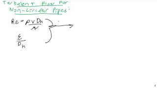
Now coming to the other case, many of the times also we do not go for only the circular conduits or the circular pipes from one point to other points okay. But when you go for a noncircular case you need to define as a equivalent flow okay. So that means we introduce a hydraulic diameters okay, it is called as hydraulic diameters.
Detailed Explanation
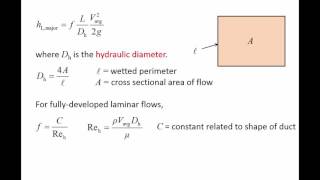
Noncircular conduits are pipes that are not circular in shape, such as rectangular or triangular pipes. When dealing with these kinds of pipes, it’s important to introduce a new measurement called 'hydraulic diameter.' This hydraulic diameter helps us to analyze the flow characteristics much like how we would with a circular pipe. Hydraulic diameter is defined as a function of the pipe's cross-sectional area and the wetted perimeter, which is the part of the perimeter that is in contact with the fluid.
Examples & Analogies
Think of it like measuring the size of a room using its area and the length of the walls that are touching the floor. Just as these dimensions help us understand how much space we have, hydraulic diameter gives us insight into how fluid will behave in a noncircular pipe.
Calculating Hydraulic Diameters
Chapter 2 of 5
🔒 Unlock Audio Chapter
Sign up and enroll to access the full audio experience
Chapter Content
which is a functions of area and wetted perimeter. The part of the perimeter which is under wetted conditions, wetted perimeters. Like for example, if I have the flow pipes, it is going through hole, so that way the total perimeter I can consider as wetted perimeter.
Detailed Explanation
Hydraulic diameter is calculated by taking four times the cross-sectional area of the pipe and dividing it by the wetted perimeter. The wetted perimeter represents the surface of the pipe that is in contact with the fluid. If the pipe is half filled with water, then only half of the perimeter is wetted. This distinction is crucial because the characteristics of the fluid flow depend significantly on this wetted area.
Examples & Analogies
Imagine a racetrack. If the track is circular, you can measure a simple diameter. But if the track is oval or another shape, you need to take into consideration the actual area where the racers can run (the part that touches the ground) as opposed to just the perimeter of the track. This analogy reflects how we define the hydraulics of noncircular conduits.
Flow Characteristics in Noncircular Conduits
Chapter 3 of 5
🔒 Unlock Audio Chapter
Sign up and enroll to access the full audio experience
Chapter Content
Now come back to the noncircular conduit like you may have a conditions where you have a only flow through this ones okay. That is called circular annulus diameter.
Detailed Explanation
In scenarios where flow occurs in noncircular conduits, we often deal with specific shapes like a circular annulus—a ring-shaped type of conduit. The hydraulic diameter can be derived from the geometry of such shapes. Different cross-sections such as rectangular or triangular can behave differently regarding fluid flow, and by understanding these shapes, we can predict flow behavior like wall shear stress and velocity distributions.
Examples & Analogies
Think of water flowing through a straw and a funnel. The straw is like a circular pipe, but a funnel can be seen as a noncircular conduit. Water flows differently through these shapes, with more turbulence in the funnel. Knowing the shape helps us predict how readily water will flow through.
Wall Stress in Noncircular Conduits
Chapter 4 of 5
🔒 Unlock Audio Chapter
Sign up and enroll to access the full audio experience
Chapter Content
Now let us come it with that when you have a noncircular pipe like if you have a pipe like a triangular shape okay. So in this case what will happen the if you have laminar flow you will have a wall stress will be maximum near the mid points of the sides.
Detailed Explanation
When analyzing fluid flow in a noncircular pipe, like a triangular pipe, the behavior of the fluid differs from circular pipes. In laminar flow, wall shear stress is highest at the midpoints of the sides and drops to zero at the vertex points of the triangle. This contrasts with circular pipes, where wall shear stress is distributed more evenly. Understanding where stress is highest helps in designing structures to resist these forces.
Examples & Analogies
Imagine a slip-n-slide made from a triangular-shaped slide. Water flows fastest at the steepest middle part and not at the edges. Knowing this helps in figuring out how strong to make the sides to support the water flow without breaking.
Turbulent Flow and Wall Shear Stress
Chapter 5 of 5
🔒 Unlock Audio Chapter
Sign up and enroll to access the full audio experience
Chapter Content
If you look at that if you have the turbulent flow same case you have a turbulent flow the velocity distributions as well as the wall shear stress distributions exchanges it. What we do it in any case of the turbulent flow we also use the Moody’s diagrams.
Detailed Explanation
In cases of turbulent flow within noncircular conduits, the distribution of velocity and wall shear stress become more complex. Unlike laminar flow, where the stress was at its maximum in specific points, turbulent flow creates swirling patterns, impacting how stress is spread throughout the pipe. Moody’s diagram is a tool employed to analyze these conditions and helps predict energy loss due to friction in various flow conditions.
Examples & Analogies
Think of a crowded swimming pool. At times, the water is calm (laminar flow), and it's easy to predict the water's motion. But when everyone splashes around (turbulent flow), the water's movement becomes chaotic and harder to predict. In a similar way, knowing how to analyze turbulent flow in pipes helps us manage these chaotic movements effectively.
Key Concepts
-
Hydraulic Diameter: A crucial calculation for noncircular conduits influencing flow analysis.
-
Wall Shear Stress: Vital in determining energy losses due to friction within pipes.
-
Reynolds Number: Key for identifying flow regimes and their dynamics in fluid mechanics.
-
Friction Factor: Essential for evaluating resistance to flow influenced by both turbulent and laminar states.
Examples & Applications
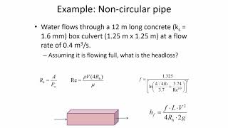
For a rectangular conduit with a width of 5 meters and height of 10 meters, the hydraulic diameter is calculated to find the flow characteristics accurately.
In sewage systems where noncircular shapes are prevalent, engineers must understand how these geometries affect flow rates and energy losses.
Memory Aids
Interactive tools to help you remember key concepts
Rhymes
In pipes so round, flow is smooth, but noncircular shapes can be a groove.
Stories
Once upon a time, water flowed in a straight circular pipe, easy and clean. But then it met a rectangle, where velocity danced differently, and taught lessons of friction and shear that engineers needed to see clearly!
Memory Tools
To remember the order: R, W, F (Reynolds number, Wall shear stress, Friction factor), think of 'Really Wet Flow.'
Acronyms
HWRF stands for Hydraulic Diameter, Wall shear stress, Reynolds number, Friction factor.
Flash Cards
Glossary
- Hydraulic Diameter
The diameter used to characterize flow in noncircular conduits, defined as four times the flow area divided by the wetted perimeter.
- Wall Shear Stress
The force exerted by a fluid on the walls of a conduit, critical for analyzing energy losses in hydraulic systems.
- Reynolds Number
A dimensionless number used to predict flow regimes, defined as the ratio of inertial forces to viscous forces in a fluid.
- Friction Factor
A dimensionless number that represents the resistance to flow in a pipe due to friction, influenced by roughness and Reynolds number.
Reference links
Supplementary resources to enhance your learning experience.