
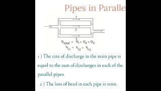
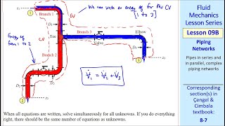
Multiple Path Pipe Flow
Enroll to start learning
You’ve not yet enrolled in this course. Please enroll for free to listen to audio lessons, classroom podcasts and take practice test.
Interactive Audio Lesson
Listen to a student-teacher conversation explaining the topic in a relatable way.
Introduction to Multiple Path Pipe Flow
🔒 Unlock Audio Lesson
Sign up and enroll to listen to this audio lesson

Welcome everyone! Today we’ll discuss multiple path pipe flow, starting with the energy gradient line. Can anyone tell me why we draw both the energy gradient line and the hydraulic gradient line?

To understand where energy is lost in the system?
Exactly, great! The energy gradient line shows us where energy is gained or lost due to elements like pumps and head losses. Remember: E stands for Energy, a mnemonic to recall every component affecting the energy in pipelines!

What about the hydraulic gradient line? What does it represent?
Good question! The hydraulic gradient line represents the pressure head in the system. Whenever we face issues calculating flows, referencing these lines helps visualize losses!

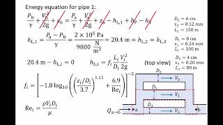
I remember that we used the Moody chart in our previous class. Can that be applied here too?
Definitely! The Moody chart relates friction factors and Reynolds numbers. Understanding these concepts aids in navigating turbulent flow in our calculations. Let's summarize: Energy and hydraulic gradient lines help show energy distribution, and the Moody chart assists in quantifying losses in turbulent flow.
Historical Perspectives
🔒 Unlock Audio Lesson
Sign up and enroll to listen to this audio lesson

Next up is the historical experiment by Nikuradse. Who can describe what he aimed to find out?

He experimented with pipe roughness and its effect on flow?
Absolutely! Nikuradse’s experiments investigated how flow characteristics change with roughness. He established relationships for turbulent flow based on his findings. Remember 'N for Nikuradse' to note that roughness impacts flow!
What about the roughness character? How does it relate to Reynolds numbers?
Great inquiry! The roughness ratio influences the transition from laminar to turbulent flow. The higher the Reynolds number, the rougher the surface affects the flow.
So how do we apply this knowledge practically?
In pipe design, understanding roughness helps predict friction factors, crucial for designing pipeline systems. Remembering Nikuradse's principles ensures better decision-making in engineering applications!
Calculating Hydraulic Diameters
🔒 Unlock Audio Lesson
Sign up and enroll to listen to this audio lesson
Now let’s tackle hydraulic diameters. Why is it important to define hydraulic diameters for noncircular conduits?
Because those shapes affect how fluid flows through them!
Exactly! We adapt our calculations using the concept of hydraulic diameter. Do you remember the formula?
Yes! It’s 4 times the area divided by the wetted perimeter.
Spot on! This helps ensure accurate flow predictions for various geometries. Now, let’s practice calculating the hydraulic diameters for different conduit shapes. Any questions?
Could we get examples of noncircular shapes?
Absolutely! We'll work on rectangles and triangles next. Remember, channeling your inner engineer will help you adapt these principles to real situations!
Introduction & Overview
Read summaries of the section's main ideas at different levels of detail.
Quick Overview
Standard
The section covers the analysis of flow in noncircular conduits, emphasizing the importance of hydraulic diameters and the challenges of calculating wall shear stress and energy losses. It recounts historical experiments that shaped our understanding of turbulent flow and introduces modern applications in engineering.
Detailed
Detailed Summary
This section unfolds the dynamics of fluid flow in noncircular conduits and highlights the phenomenon of multiple path pipe flow. The key concepts addressed include the significant role of hydraulic diameters in defining flow characteristics in non-standard pipe shapes. The concept of wall shear stress is explored alongside empirical relationships derived from historical experiments, notably the contributions of Nikuradse in the 1930s.
The section initiates a discussion on the significance of the energy gradient line and hydraulic gradient line for visualizing energy distribution in the fluid flow systems. These concepts are essential in recognizing energy losses such as major losses and minor losses within pipe systems.
By leveraging experimental setups that replicate conditions of turbulent flow, the material illuminates the relationship between flow velocity, wall shear stress, and roughness, ultimately leading to the establishment of Moody's chart which is crucial for fluid mechanics applications. Furthermore, as the discussion pivots to the challenges associated with noncircular conduits, it elucidates how hydraulic diameters are calculated for various shapes including rectangles and triangles, with a focus on adapting the flow equations accordingly.
In essence, the section provides a comprehensive overview of the interplay between pipe geometry and fluid dynamics, forming a fundamental basis for solving practical engineering problems related to fluid flow.
Youtube Videos


Audio Book
Dive deep into the subject with an immersive audiobook experience.
Introduction to Noncircular Conduits
Chapter 1 of 5
🔒 Unlock Audio Chapter
Sign up and enroll to access the full audio experience
Chapter Content
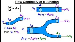
Now, coming to the other case, many of the times also we do not go for only the circular conduits or the circular pipes from one point to other points okay. But when you go for a noncircular case you need to define as a equivalent flow okay. So that means we introduce a hydraulic diameter which is a functions of area and wetted perimeter.
Detailed Explanation
This chunk introduces the concept that not all fluid flow occurs in circular pipes. Instead, flow can occur in noncircular conduits, which require different approaches for analysis. A key term introduced here is 'hydraulic diameter', which allows us to characterize these noncircular flows similarly to circular ones. The hydraulic diameter is calculated using the area of the flow and the wetted perimeter (the part of the perimeter that is in contact with the fluid). This concept is essential when studying different shapes of conduits, such as rectangular or triangular sections.
Examples & Analogies
Imagine using a garden hose to water your plants. If the hose is circular, you can easily measure how much water flows through it. But if you used a long, flat dish instead of a hose, you'd need to figure out how to measure the flow through it using its unique shape. That's what hydraulic diameter helps us do - it lets us find a consistent way to measure flow in both round hoses and flat dishes.
Calculating Hydraulic Diameter
Chapter 2 of 5
🔒 Unlock Audio Chapter
Sign up and enroll to access the full audio experience
Chapter Content
the hydraulic diameters okay, it is called as hydraulic diameters, which is a functions of area and wetted perimeter. The part of the perimeter which is under wetted conditions.
Detailed Explanation
The hydraulic diameter is a critical value in fluid mechanics, especially for noncircular conduits. It is calculated by a formula that takes into account both the cross-sectional area of the conduit's flow and the wetted perimeter. For fully submerged circular conduits, the hydraulic diameter equals the geometric diameter, but for partially filled cross-sections, only the wetted perimeter is considered. Understanding this diameter is crucial for calculating flow rates and determining pressure losses in different conduit shapes.
Examples & Analogies
Think of a swimming pool that is shaped like a rectangle. The 'wetted perimeter' would be the sides of the pool that the water touches. If the pool is empty, you can’t simply use the full length of the sides to determine how much water flows in - you only care about the sides that are actually in contact with the water when it is filled to a certain level. The hydraulic diameter helps in finding the flow characteristics based on those contact points.
Flow Characteristics in Noncircular Conduits
Chapter 3 of 5
🔒 Unlock Audio Chapter
Sign up and enroll to access the full audio experience
Chapter Content
Similar way if you have a rectangular cross-sections and flow through these systems, I can define it what will be the area and the wetted perimeters. That is what will give me the hydraulics diameter.
Detailed Explanation
This chunk addresses how to define flow characteristics for rectangular and triangular cross-sections. The formula remains similar: by calculating the area and wetted perimeter for these shapes, we can derive their hydraulic diameter. This helps engineers and scientists apply similar principles used for circular pipes to noncircular designs, ensuring they can analyze flow dynamics effectively across different shapes.
Examples & Analogies
Imagine a canal where the water flows in a rectangular shape. To figure out how fast it flows, you would measure the width and the depth of the water. From those measurements, you can find the hydraulic diameter - just like you would if the water was flowing through a round pipe. This gives you a way to understand how the shape of the canal impacts water speed, just as it would with a standard pipe.
Velocity Distribution in Noncircular Flows
Chapter 4 of 5
🔒 Unlock Audio Chapter
Sign up and enroll to access the full audio experience
Chapter Content
Now, if you have a noncircular pipe like if you have a pipe like a triangular shape...maximum at the midpoint of the side, wall shear stress becomes zero at this point.
Detailed Explanation
In this section, the behavior of fluid flow in noncircular pipes, such as triangular shapes, is discussed. It highlights how wall shear stress is distributed differently in such flows compared to circular pipes. In a triangular conduit, the maximum shear stress occurs at the midpoints of the sides, whereas at the corners, the shear stress drops to zero. Understanding this distribution is vital for predicting how the fluid will behave under different conditions and is critical for designing systems that handle noncircular flow.
Examples & Analogies
Consider a traffic intersection shaped like a triangle. Cars (representing fluid) will experience the most congestion in the middle of each side, where they need to slow down to maneuver. Meanwhile, at the points (corners of the triangle), there are fewer cars, reflecting the lesser 'shear stress' in fluid dynamics. Recognizing this helps traffic engineers optimize the flow pattern, similar to how fluid dynamicists manage flow in noncircular pipes.
Turbulent Flow in Noncircular Conduits
Chapter 5 of 5
🔒 Unlock Audio Chapter
Sign up and enroll to access the full audio experience
Chapter Content
When you have the turbulent flow same case you have a turbulent flow...and these are responsible for the mass actions, momentum actions through these the flow systems.
Detailed Explanation
This chunk explains the nature of turbulent flow within noncircular conduits. Unlike laminar flow, turbulent flow is characterized by chaotic, unpredictable fluctuations that enhance mixing and momentum transfer within the fluid. In noncircular pipes, these turbulence effects are critical as they affect how energy is lost due to friction against the walls and how effectively the flow moves through the conduit. Understanding these actions helps in designing pipes that minimize energy losses and optimize flow.
Examples & Analogies
Imagine a busy restaurant kitchen. When chefs (fluid particles) are working quietly, they can move around easily (laminar flow). But when they start moving quickly and bump into each other while multitasking (turbulent flow), things get chaotic and messy! Understanding turbulent flow helps chefs organize their spaces effectively, just like creating efficient noncircular conduits does in fluid systems.
Key Concepts
-
Multiple Path Pipe Flow: Refers to the flow of fluids in systems where pipes are interconnected, leading to complex flow patterns.
-
Hydraulic Diameter: An essential calculation for determining flow characteristics in noncircular conduits.
-
Wall Shear Stress: Critical for understanding how fluid interacts with the surface of conduits, influencing energy losses.
-
Energy Gradient Line: Illustrates energy changes throughout the fluid flow process, assisting in identifying losses.
-
Hydraulic Gradient Line: Indicates the pressure energy available in a fluid system and guides engineers in flow assessment.
Examples & Applications
When determining the flow through a rectangular channel, calculate the hydraulic diameter to ensure accuracy in predicting flow rates and shear stresses.
In designing a drainage system, engineers must consider roughness and calculate friction factors using Moody's chart for reliable predictions.
Memory Aids
Interactive tools to help you remember key concepts
Rhymes
When the fluid flows in a pipe so round, energy and pressure are tightly bound.
Stories
Imagine Nikuradse as a fluid detective, uncovering the secrets of how pipe roughness plays with turbulence.
Memory Tools
Remember 'R.E.A.C.T.': Roughness, Energy Gradient, Area, Conduit, Turbulent flow.
Acronyms
R.E.C. - Roughness, Energy, Calculations - the key components in analyzing pipe flow.
Flash Cards
Glossary
- Hydraulic Diameter
A characteristic length used in noncircular conduits calculated as 4 times the area divided by the wetted perimeter.
- Reynolds Number
A dimensionless number that characterizes flow regimes in fluids, indicating whether flow is laminar or turbulent.
- Moody Chart
A graphical representation that specifies the relationship between Reynolds numbers and friction factors for various flow regimes.
- Wall Shear Stress
The shear stress exerted by a fluid on the boundary of a pipe or conduit; a critical factor affecting flow characteristics.
- Energy Gradient Line
A line that represents the total energy head per unit weight of fluid throughout a flow system.
- Hydraulic Gradient Line
A line showing the pressure head in a fluid flow system, indicating the hydraulic energy available.
Reference links
Supplementary resources to enhance your learning experience.