
BREAK COMMAND
Enroll to start learning
You’ve not yet enrolled in this course. Please enroll for free to listen to audio lessons, classroom podcasts and take practice test.
Interactive Audio Lesson
Listen to a student-teacher conversation explaining the topic in a relatable way.
Introduction to the BREAK Command
🔒 Unlock Audio Lesson
Sign up and enroll to listen to this audio lesson

Today, we will delve into the BREAK command. This command allows us to cut an object into two separate parts. Can anyone share why you think this might be useful?

It could be useful for editing shapes without redrawing elements!
Exactly! Imagine needing to remove a portion of a line or shape without starting from scratch. This saves time and maintains precision. Remember, we can specify the first break point and the second one to achieve the desired results.

How do you actually implement that in CAD?
Good question! You initiate the command with 'BREAK' or 'BR', select the object, then specify your break points. Make sure you're precise!
Practical Applications of the BREAK Command
🔒 Unlock Audio Lesson
Sign up and enroll to listen to this audio lesson

Let's explore how this command can be applied. Imagine designing a wall; if we need to create a door opening, we can break the wall object.

So it helps in adjustments without redrawing every line?
Precisely! Does anyone recall how to connect segments after we break them?

Could we use the CHAMFER or FILLET commands?
Yes! The CHAMFER command connects two edges at an angle, and FILLET adds a rounded arc. These tools complement our work with the BREAK command by providing seamless transitions.
Advanced Features and Tips
🔒 Unlock Audio Lesson
Sign up and enroll to listen to this audio lesson
As you advance in CAD, you'll find shortcuts and methods to streamline your use of the BREAK command. For example, using it in combination with other commands can enhance design efficiency.
Is there a way to undo if I make a mistake?
Great thought! There’s a straightforward method; simply use the 'UNDO' command. It’s crucial to have that backup in case a cut doesn’t turn out as planned.
What about contexts where we shouldn’t use BREAK?
An important consideration! Avoid using BREAK on complex objects without analyzing the consequences. Sometimes, it’s better to use layers or separate entities for clarity.
Introduction & Overview
Read summaries of the section's main ideas at different levels of detail.
Quick Overview
Standard
The BREAK command allows users to modify existing objects by cutting them into two parts or deleting sections between specified break points. This section also covers related modification tools such as CHAMFER and FILLET, which enhance the drawing capabilities of users.
Detailed
BREAK COMMAND Overview
The BREAK command is used in Computer Aided Design (CAD) to divide an object into two distinct parts at chosen points or to erase part of an object between two predetermined points. This command is essential for making modifications to geometrical shapes, enabling more streamlined designs. Understanding how to effectively use the BREAK command and its relationship with other tools like CHAMFER (which connects non-parallel lines) and FILLET (which connects two objects with a rounded arc) is fundamental for any CAD user to enhance their drawing precision and efficiency.
Youtube Videos


Audio Book
Dive deep into the subject with an immersive audiobook experience.
Purpose of the Break Command
Chapter 1 of 2
🔒 Unlock Audio Chapter
Sign up and enroll to access the full audio experience
Chapter Content
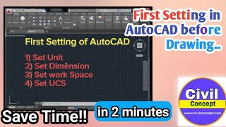
This method is used to cut an object into two parts at selected point (or) to remove part of the object in between two selected points.
Detailed Explanation
The Break command is a function in CAD software that allows users to divide a continuous object into two separate sections. This could be useful in various drawing applications where you may need to create openings in walls or modify existing shapes. Users can select the object they wish to break, choose a specific point to initiate the break, and a second point to complete the break action.
Examples & Analogies
Think of the Break command like using scissors to cut a piece of paper. Just as you can choose where to start cutting and where to stop, in CAD, you select the points where you want to divide the object into two parts.
Command Syntax for the Break Command
Chapter 2 of 2
🔒 Unlock Audio Chapter
Sign up and enroll to access the full audio experience
Chapter Content
COMMAND: BREAK or BR.
Select object; select an object or specify the first break point of an object.
Enter second point; specify the second break point.
Detailed Explanation
To use the Break command, you begin by entering the command either by typing 'BREAK' or its shortcut 'BR'. Next, you need to select the object you want to break. Once the object is selected, you specify the first break point—this is the starting point where the break will occur. After this, you need to input a second point that will determine where the break will end. This effectively creates two separate parts of the object.
Examples & Analogies
Imagine you have a rope and you want to cut it. First, you choose where to start cutting (the first point), and then you locate where you want to end the cut (the second point). After you finish, you have two pieces of rope, just like how the Break command gives you two separate parts of a drawing object.
Key Concepts
-
BREAK Command: Cuts an object into two parts.
-
CHAMFER: Connects two non-parallel lines with a beveled edge.
-
FILLET: Connects two lines with a smooth arc.
Examples & Applications
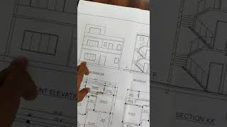
Using the BREAK command to create a door opening in a wall.
Applying the CHAMFER command to connect two intersecting lines at an angle.
Using the FILLET command to round the corners of overlapping shapes.
Memory Aids
Interactive tools to help you remember key concepts
Rhymes
If you need to break and cannot fake, Clip apart your design for precision's sake.
Stories
Imagine a carpenter needing to create a door in the middle of a long wooden plank. They must carefully cut to keep it functional and neat. Just like this carpenter, the BREAK command allows CAD users to slice through objects without remake.
Memory Tools
To remember the sequence of using BREAK: 'B' for Begin, 'S' for Select, 'D' for Define points.
Acronyms
BREAK
- Begin command; R - Rest the object; E - Enter breakpoints; A - Adjust as needed; K - Keep the design clean.
Flash Cards
Glossary
- BREAK Command
A command in CAD used to cut an object into two parts or to erase a portion of an object between selected points.
- CHAMFER
A command that connects two non-parallel lines with a beveled line, enhancing the transitions between lines.
- FILLET
A command that rounds the corner where two lines meet by creating a smooth curve.
- UNDO
A command used to revert the last action taken in CAD, allowing the user to correct mistakes.
Reference links
Supplementary resources to enhance your learning experience.