
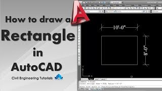
RECTANGLE COMMAND
Enroll to start learning
You’ve not yet enrolled in this course. Please enroll for free to listen to audio lessons, classroom podcasts and take practice test.
Interactive Audio Lesson
Listen to a student-teacher conversation explaining the topic in a relatable way.
Introduction to Rectangle Command
🔒 Unlock Audio Lesson
Sign up and enroll to listen to this audio lesson

Today, we're going to learn about the Rectangle Command in CAD. This command allows us to create rectangles efficiently. Can anyone tell me how many corners a rectangle has?

Four corners!
Exactly! To create a rectangle, we start by picking one corner. Then, we specify the opposite corner. This rectangle will be treated as one object. Can anyone guess why this is useful?

So we can move or modify it easily without affecting the rest of the drawing?
That's correct! Remember, with the Rectangle Command, you can also add options like chamfer or fillet to the corners for a neat finish.
Let's summarize: We use the command 'RECTANGLE' or simply type 'rec' to initiate. Then we select our first corner and the opposite corner. Any questions before we proceed?
Using Parameters with the Rectangle Command
🔒 Unlock Audio Lesson
Sign up and enroll to listen to this audio lesson

Now that we've covered how to draw a basic rectangle, let's delve into how we can use parameters such as chamfer and fillet. Can someone tell me the difference between these two?

Chamfer is where you cut off the corner, and fillet is where we round the corner, right?
Exactly! Using these parameters improves the aesthetics of our designs. When we execute the command, we can specify these options to alter how the rectangle looks immediately.

How do we set the thickness for the rectangle?
Great question! During drawing, we can specify the 'thickness' option after choosing the corners. This allows us to create a rectangle with depth, which is useful in 3D designs.
So, when we summarize, remember that the Rectangle Command is not just about the shape; we can enhance it with features like chamfer, fillet, and thickness. Make sure to practice applying these features!
Practical Application of Rectangle Command
🔒 Unlock Audio Lesson
Sign up and enroll to listen to this audio lesson
Let's talk about where the Rectangle Command might be used in real projects. Can anyone think of applications in architectural design?
Creating the foundation layout in a building design?
Absolutely! We often use rectangles to depict walls or rooms in architectural blueprints. What about in mechanical design?
We might create bases for machines or components?
Exactly! The Rectangle Command helps define parameters and spaces in both fields. Understanding this tool will make you more effective as designers.
In summary, rectangles are fundamental in various designs; mastering the Rectangle Command enables us to create detailed and accurate representations.
Introduction & Overview
Read summaries of the section's main ideas at different levels of detail.
Quick Overview
Standard
The Rectangle Command allows users to create rectangles as single objects within CAD programs. This section details how to utilize the command effectively, including the entry of corners and additional parameters such as chamfer and fillet.
Detailed
Rectangle Command in Computer-Aided Design
The Rectangle Command is essential for creating rectilinear shapes in computer-aided design (CAD) applications. This command, represented by 'RECTANGLE' or 'rec', facilitates the drawing of a rectangle by allowing the user to specify two opposite corners of the shape. Each rectangle is treated as a single object, making it easier to manipulate within the software.
Key Features:
- Parameters: Users can customize the rectangle with options for chamfering, filleting, thickness, and width.
- Usage: The command is executed by first specifying one corner, then the diagonal opposite corner.
- Applications: Ideal for architectural designs and layouts where rectangles serve as walls, windows, or areas of interest.
Understanding how to implement the Rectangle Command effectively enhances productivity in CAD, as it streamlines the creation of complex structures.
Youtube Videos


Audio Book
Dive deep into the subject with an immersive audiobook experience.
Understanding the Rectangle Command
Chapter 1 of 3
🔒 Unlock Audio Chapter
Sign up and enroll to access the full audio experience
Chapter Content
COMMAND: RECTANGLE or rec.
Detailed Explanation
The Rectangle command in computer-aided drawing software allows users to create rectangles, which are geometric shapes characterized by having opposite sides that are equal in length and four right angles. To execute this command, you can type 'RECTANGLE' or simply 'rec' in the command prompt. This activates the rectangle drawing tool.
Examples & Analogies
Imagine you're a carpenter laying down the foundation for a rectangular patio. Just like measuring and marking the corners before you start building, the Rectangle command lets you define the corners of your shape on the computer.
Defining the Rectangle Corners
Chapter 2 of 3
🔒 Unlock Audio Chapter
Sign up and enroll to access the full audio experience
Chapter Content
Chamfer/ Elevation/ Fillet/ Thickness/ Width/
Detailed Explanation
To create a rectangle, you first need to specify the first corner of the rectangle by clicking on a point in your drawing area. This is the starting reference point. After selecting the first corner, you then choose the opposite corner of the rectangle by clicking another point. The software will automatically calculate the dimensions of the rectangle based on these two corners.
Examples & Analogies
Think of drawing a rectangle on paper. You start by putting a dot in one corner to mark where you want one edge to begin. Then, you decide how far you want to go to create the opposite edge and mark that point as well. This visual process directly translates to how the Rectangle command works in software.
Options for Rectangle Customization
Chapter 3 of 3
🔒 Unlock Audio Chapter
Sign up and enroll to access the full audio experience
Chapter Content
Chamfer/ Elevation/ Fillet/ Thickness/ Width
Detailed Explanation
In addition to simply drawing a rectangle, the command allows for customization options. You can specify features such as 'Chamfer' to create beveled edges, or 'Fillet' to round the corners. 'Thickness' and 'Width' allow for variations in the physical dimensions of the rectangle, which can be important for detailed architectural drawings.
Examples & Analogies
Imagine designing a modern table. You can choose sharp edges for a sleek look or rounded edges for safety. Similarly, the Rectangle command provides options to customize your rectangle's appearance and functionality based on your design needs.
Key Concepts
-
Rectangle Command: Essential for creating rectangles in CAD.
-
Chamfer: Allows cutting the corners of a rectangle.
-
Fillet: Used to round the corners of a rectangle.
-
Thickness: Specifies depth for 3D rectangles.
Examples & Applications
Example of a building layout using rectangles to represent rooms and walls.
An illustration of a mechanical part designed using rectangles to outline its profile.
Memory Aids
Interactive tools to help you remember key concepts
Rhymes
In CAD with a rectangle I freely play, two corners defined in a straightforward way.
Stories
Imagine a builder drawing rooms on his blueprint. With a single command, he can make rectangles swiftly, reminding him of the efficiency needed on the job.
Memory Tools
Remember CFT: 'C' for Chamfer, 'F' for Fillet, 'T' for Thickness—these define the rectangle's behavior!
Acronyms
RCD
'Rectangle Creates Design' – essential for every CAD project!
Flash Cards
Glossary
- Rectangle Command
A CAD command used to create a rectangle by specifying two opposite corners.
- Chamfer
A bevel cut applied to the corners of the rectangle.
- Fillet
A rounded corner applied to the rectangles.
- Thickness
The depth of a rectangle pre-defined in CAD to create a 3D object.
Reference links
Supplementary resources to enhance your learning experience.