
3D Drafting and Isometric Views
Enroll to start learning
You’ve not yet enrolled in this course. Please enroll for free to listen to audio lessons, classroom podcasts and take practice test.
Interactive Audio Lesson
Listen to a student-teacher conversation explaining the topic in a relatable way.
Introduction to 3D Drafting
🔒 Unlock Audio Lesson
Sign up and enroll to listen to this audio lesson

Today, we're exploring how 3D drafting enhances our workflow in civil engineering. Can anyone tell me why 3D modeling might be advantageous over 2D drafting?

It helps with visualization and gives a better understanding of the project.
Exactly! It allows us to see how structures fit in with their surroundings. One of the tools we’ll focus on is the ‘extrude’ command. It lets you extend a 2D object into a 3D shape.

How does 'extrude' work exactly?
Great question! You simply select the shape and specify the height for it to rise into the third dimension. Memory aid: Think 'extrude' = 'extend out'!

Could you show an example of when to use this?
Certainly! If you're modeling a wall from a floor plan, you would extrude the outline to give it height.
To recap, 3D drafting offers improved visualization, and tools like 'extrude' create depth from our 2D designs.
Other 3D Tools in AutoCAD
🔒 Unlock Audio Lesson
Sign up and enroll to listen to this audio lesson

Let's dive deeper into more 3D tools in AutoCAD. Besides 'extrude', we have 'revolve', 'sweep', and 'presspull'. Who can explain what 'revolve' does?

Doesn't it turn a shape around an axis?
Correct! It transforms a profile into a full solid. For example, creating a vase shape would involve revolving a circle around its center axis.
What about 'sweep'? I’m a bit confused about its function.
'Sweep' takes a 2D shape and follows a specified path, making it perfect for modeling complex profiles like handrails. Think of it as sweeping a path with a brush.
And 'presspull'?
'Presspull' allows direct interaction with shapes; you pull on a 2D outline to create forms. It's like pulling dough from a flat surface!
To summarize, using these tools—'revolve' for rotations, 'sweep' for paths, and 'presspull' for interactive shaping—helps us build more complex 3D models from our foundational designs.
Isometric Drawing Techniques
🔒 Unlock Audio Lesson
Sign up and enroll to listen to this audio lesson
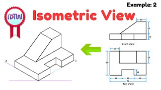
Now, let’s discuss isometric drawings. They are crucial for representing 3D objects in a 2D space. How would you define isometric drawings?
I believe they show dimensions equally without distortion?
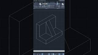
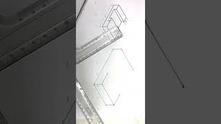
Yes! Isometric drawings provide a clear viewpoint. You can switch to an isometric grid in AutoCAD using the command 'ISODRAFT'.
What about shapes like pipes? How would we draw those?
For pipes, we use the 'ELLIPSE' command with the isocircle option. This helps in accurately portraying round objects in isometric view.
Can you explain why isometric views are commonly used in plumbing?
Isometric views simplify the complexity of 3D structures into clear, understandable components, making it easier to visualize installations.
In summary, isometric drawings provide clarity without perspective changes, critical for fields requiring precise dimensional representation.
Introduction & Overview
Read summaries of the section's main ideas at different levels of detail.
Quick Overview
Standard
As 2D drawings dominate civil engineering, 3D drafting is gaining traction. This section explores the AutoCAD tools for 3D design such as extrude, revolve, sweep, and presspull. It also covers isometric drawing practices, particularly beneficial for applications like plumbing and piping.
Detailed
3D Drafting and Isometric Views
In civil engineering, while 2D drawings remain prevalent, the utilization of 3D drafting continues to grow due to its advantages in visualization and accuracy. This section discusses several critical tools in AutoCAD essential for creating 3D models:
- Extrude: Allows the user to extend 2D shapes into 3D forms by defining a height.
- Revolve: Creates 3D objects by rotating a 2D profile around an axis.
- Sweep: Generates 3D objects by moving a shape along a defined path.
- Presspull: Utilizes the mouse to pull 2D shapes into a desired 3D representation.
Furthermore, understanding isometric drawings—often applied in contexts such as pipelines and plumbing—is crucial. Utilizing the isometric grid through the ISODRAFT command and the ELLIPSE command for isocircle options facilitates the accurate representation of these objects.
Youtube Videos
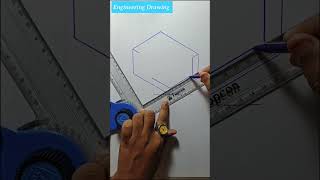
![How to draw isometric drawing [drawing no 1] #shorts #shortsvideo #youtubeshorts #3d #drawing](https://img.youtube.com/vi/OsMGBSdX2Fs/mqdefault.jpg)

Audio Book
Dive deep into the subject with an immersive audiobook experience.
Introduction to 3D Drafting
Chapter 1 of 3
🔒 Unlock Audio Chapter
Sign up and enroll to access the full audio experience
Chapter Content
Although civil engineers primarily use 2D drawings, 3D drafting is increasingly common.
Detailed Explanation
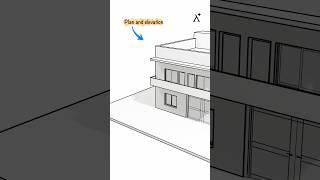
In civil engineering, the traditional approach has been to create two-dimensional (2D) representations of structures, which include plans, sections, and elevations. However, as technology and software capabilities have advanced, the use of three-dimensional (3D) drafting has become more popular. 3D drafting offers a more comprehensive visualization of a project, helping engineers and architects better understand spatial relationships and scale in their designs.
Examples & Analogies
Think of 3D drafting like the difference between looking at a blueprint of your house versus walking through it. A blueprint (2D) gives you the layout but doesn't show the furniture, colors, or actual spatial relationships as you would see in a physical space.
3D Tools in AutoCAD
Chapter 2 of 3
🔒 Unlock Audio Chapter
Sign up and enroll to access the full audio experience
Chapter Content
3D Tools in AutoCAD
- Extrude
- Revolve
- Sweep
- Presspull
Detailed Explanation
AutoCAD provides several tools specifically designed for creating 3D models. Each of these tools serves different purposes:
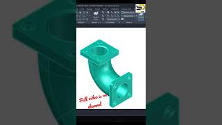
- Extrude: This tool allows you to extend a 2D shape vertically into a 3D object. For instance, if you have a circle, extruding it will turn it into a cylinder.
- Revolve: This creates a 3D object by rotating a 2D profile around an axis. For example, if you take a triangle and revolve it around one of its edges, it forms a cone.
- Sweep: With the sweep tool, you can take a 2D shape and move it along a 3D path. Imagine dragging a circle along a curved line to create a pipe.
- Presspull: This is similar to extrude but more interactive; you can click on a face and pull it to create a 3D shape dynamically.
Examples & Analogies
Consider a potter at a wheel shaping clay. The potter can 'extrude' a ball of clay into a pot by pressing upwards, 'revolve' a piece of clay to create a round shape, and 'sweep' or shape a long piece of clay into a handle as it follows a path.
Isometric Drawing
Chapter 3 of 3
🔒 Unlock Audio Chapter
Sign up and enroll to access the full audio experience
Chapter Content
Isometric Drawing
Used for pipelines, plumbing, and architectural presentation.
- Switch to isometric grid: ISODRAFT
- Use ELLIPSE with isocircle option for pipes
Detailed Explanation
An isometric drawing is a 3D representation on a 2D plane, where the three dimensions are depicted at equal angles (120 degrees). This type of drawing is particularly useful for showing complex systems, such as plumbing and piping, where clarity and detail are essential. In AutoCAD, you can switch to an isometric grid using the 'ISODRAFT' command, which helps you draw accurately in an isometric perspective. Additionally, for circular features like pipes, the 'ELLIPSE' command can be used with the isocircle option to create oval shapes that represent the circular pipe viewed in isometric.
Examples & Analogies
Imagine drawing a box from a corner viewpoint. The sides will appear in an equal slant, not just in flat lines. It’s like looking at a cube from the corner; you can see three sides at once, providing a clear representation of the object's volume and space in a way that’s more informative than traditional flat drawings.
Key Concepts
-
3D Drafting: The process of creating three-dimensional objects, providing a more accurate representation than 2D drawings.
-
Isometric Views: A type of drawing that allows for the representation of three-dimensional objects on a two-dimensional plane without perspective distortion.
Examples & Applications
A civil engineer uses the 'extrude' tool to create a 3D model of a foundation from the 2D layout.
Isometric drawing for a plumbing layout that shows pipes and fittings clearly without distortion.
Memory Aids
Interactive tools to help you remember key concepts
Rhymes
To build up, give it height, use 'extrude' and get it right!
Stories
Imagine a sculptor who takes a flat shape, like clay, and turns it into a magnificent vase by rolling it around a potter's wheel—this is like the 'revolve' command in 3D drafting.
Memory Tools
Remember: 'E-R-S-P' for the sequence of commands: 'Extrude, Revolve, Sweep, and Presspull'.
Acronyms
For Isometric drawing remember 'I-D-P' – Isometric, Depth, Proportional.
Flash Cards
Glossary
- Extrude
A tool in AutoCAD that allows the creation of 3D objects by extending a 2D shape into three-dimensional space.
- Revolve
A command used to create a 3D object by rotating a 2D shape around an axis.
- Sweep
A tool that creates a 3D object by moving a 2D profile along a specified path.
- Presspull
An interactive command in AutoCAD that pulls or pushes 2D objects into a 3D shape.
- Isometric Drawing
A method of visually representing three-dimensional objects in two dimensions, maintaining proportional dimensions along three axes.
Reference links
Supplementary resources to enhance your learning experience.