
Plotting and Printing Drawings
Enroll to start learning
You’ve not yet enrolled in this course. Please enroll for free to listen to audio lessons, classroom podcasts and take practice test.
Interactive Audio Lesson
Listen to a student-teacher conversation explaining the topic in a relatable way.
Plot Settings
🔒 Unlock Audio Lesson
Sign up and enroll to listen to this audio lesson

Let's start with plot settings. Can anyone tell me what key components we need to set before we print our CAD drawings?

Do we need to choose a paper size?
Absolutely, paper size is crucial. We typically select sizes like A4, A3, or A1 depending on the project. What else needs to be set?

We should also define the plot area, right?
Yes, the plot area can be set to a specific window or to the entire layout. It defines what parts of the drawing will appear on the printed page. Great points! Now, can anyone remember what we use to determine how large the final output will be?

The plot scale?
Correct! The plot scale, such as 1:100 or 1:50, tells us how measurements on our drawing will translate to real-world sizes. Lastly, we also need to choose a plot style, either monochrome or color. That's pivotal for clarity.
To recap, plot settings include paper size, plot area, plot scale, and plot style. Understanding these components ensures that our CAD drawings look professional when printed.
Using Viewports
🔒 Unlock Audio Lesson
Sign up and enroll to listen to this audio lesson

Next, let's talk about viewports. Why do we utilize viewports when preparing to print CAD drawings?

So we can show different parts of the drawing at varying scales!
Exactly! Viewports allow us to display multiple perspectives or details, which is particularly useful for providing clarity in complex designs. Can anyone think of situations where that would be necessary?
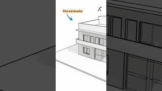
In architectural drawings, to show floor plans and elevations together!
Exactly, that’s a great example! When we use viewports effectively, it can significantly enhance the readability of our plans. Remember that you can adjust the scale in each viewport to suit the details being shown.
In summary, viewports are essential for presenting multiple views at different scales, which aids in the comprehensive understanding of a project.
Title Block and Border Importance
🔒 Unlock Audio Lesson
Sign up and enroll to listen to this audio lesson
Now let’s discuss the title block and border. What information do we usually include in our title blocks?
The drawing title, scale, and our names!
Exactly! Title blocks typically include vital details like the drawing title, drafter’s name, date, and sheet number. Why do you think it's important to have these in our prints?
So people know what the drawing is about and who created it!
Right! Including this information maintains professionalism and clarity. It's easy to confuse multiple sheets without clear identifiers. Now, how do we incorporate these title blocks into our drawings?
We can create them as blocks in CAD!
Perfect! Creating title blocks as blocks makes them reusable and consistent across multiple drawings. To sum up, title blocks and borders are crucial for professionalism in printed drawings.
Introduction & Overview
Read summaries of the section's main ideas at different levels of detail.
Quick Overview
Standard
In this section, we discuss plot settings, the use of viewports in layout, and the importance of integrating title blocks and borders when printing CAD drawings, which ensure clarity and professionalism in print outputs.
Detailed
Plotting and Printing Drawings
In the realm of Computer-Aided Drafting (CAD), plotting and printing drawings is a critical step in the final phases of a design project. This section outlines the essential components involved in the plotting process, which includes:
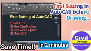
- Plot Settings: Before plotting, it is crucial to configure the plot settings which comprise the selection of paper size (such as A4, A3, A1, etc.), determining the plot area - whether it will be a specific window or the entire layout, adjusting the plot scale (commonly seen as 1:100 or 1:50), and selecting a suitable plot style table which can be monochrome or color.
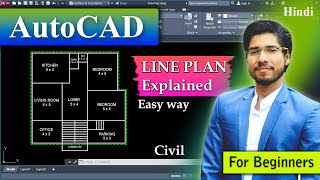
- Viewports in Layout: Viewports allow users to display different views of the drawing at various scales in paper space, enhancing the understanding of the drawn components from multiple perspectives.
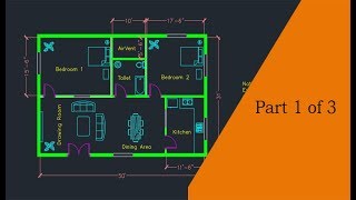
- Title Block and Border: Including a standardized title block, which often can be created as a block in CAD, is essential for conveying important information such as the drawing title, name of the draftsperson, scale, date, and sheet number. This ensures that the printed drawings are professional and organized, making them easier to read and understand.
Through these elements, the section emphasizes how effective plotting and printing procedures contribute to the overall quality of CAD drawings in civil engineering.
Youtube Videos

Audio Book
Dive deep into the subject with an immersive audiobook experience.
Plot Settings
Chapter 1 of 3
🔒 Unlock Audio Chapter
Sign up and enroll to access the full audio experience
Chapter Content
- Paper size (A4, A3, A1, etc.)
- Plot area: Window or Layout
- Plot scale: 1:100, 1:50 etc.
- Plot style table: Monochrome or color
Detailed Explanation
This chunk provides the essential plot settings you need to configure before printing a drawing. Each aspect is crucial for ensuring your drawing appears as intended on paper. The paper size can vary depending on the requirements of your project; common sizes include A4, A3, and A1. You also need to decide whether to plot a specific 'Window' area or the entire 'Layout'. The plot scale represents how the dimensions in your drawing translate to the printed page; for instance, a scale of 1:100 means that 1 unit in the drawing equals 100 units in reality. Finally, choose a plot style table that determines if the printout will be in monochrome (black and white) or color.
Examples & Analogies
Think of plot settings like preparing a recipe. Just as you choose the size of your baking pan, the temperature, and whether to use a specific type of frosting, in CAD you choose the paper size, scale, and color scheme to make sure the final product meets your expectations.
Viewports in Layout
Chapter 2 of 3
🔒 Unlock Audio Chapter
Sign up and enroll to access the full audio experience
Chapter Content
Used to display multiple views at different scales in paper space.
Detailed Explanation
This chunk talks about viewports, which are essential for organizing how different views of a CAD drawing are presented on a single sheet of paper. Each viewport can show a different part of your drawing, potentially at various scales. This allows you to highlight important areas without cluttering the design, ensuring that valuable details are visible and appropriately sized for the reader.
Examples & Analogies
Imagine a gallery exhibit where art pieces are arranged in separate frames; each frame could be at a different size or even show a different angle of the same artwork. Similarly, viewports in a layout act like those frames, allowing different perspectives of your project to be displayed together.
Title Block and Border
Chapter 3 of 3
🔒 Unlock Audio Chapter
Sign up and enroll to access the full audio experience
Chapter Content
- Add standardized title blocks (can be a block)
- Include drawing title, name, scale, date, sheet number
Detailed Explanation
The final chunk discusses the title block and border of a drawing, which are critical for providing context and information about the drawing. A title block typically contains essential details such as the name of the drawing, who created it, the scale used, the date of creation, and the sheet number. This information is standardized to ensure consistency across different drawings, making it easier for anyone reviewing them to understand and locate relevant details quickly.
Examples & Analogies
Think of the title block as a book cover and the border as the frame around a picture. Just as a book cover gives you a glimpse of the story inside and the author's name, the title block provides crucial information about the drawing, while the border neatly frames everything, creating a polished look.
Key Concepts
-
Plot Settings: Essential configurations for printing, including paper size and plot scale.
-
Viewports: Areas in paper space used to display different views at various scales.
-
Title Block: Section of a drawing containing vital information about the project.
-
Border: The outer margin of the drawing that maintains print formatting.
Examples & Applications
Using an A3 paper size to print a detailed site plan.
Creating a title block that includes the drawing title, the drafter's name, and the date for a civil engineering project.
Memory Aids
Interactive tools to help you remember key concepts
Rhymes
When you plot, don't forget, set your scale, and size, you won't regret.
Stories
Imagine you are a chef preparing a intricate recipe, and every ingredient (plot setting) needs to be measured (scaled) perfectly to ensure the dish comes out beautifully (the printed drawing).
Memory Tools
PPT - Paper size, Plot area, Title block represent key plot elements.
Acronyms
VPP - Viewports Present Portions, reminding you of the role of viewports in showcasing different drawing parts.
Flash Cards
Glossary
- Plot Settings
Configurations that determine how a drawing is printed, including paper size, plot area, plot scale, and plot style.
- Viewports
Defined areas in the paper space of a CAD layout that display specific views of the drawing at various scales.
- Title Block
A standardized section of a drawing that includes important information such as the title, drafter's name, scale, date, and sheet number.
- Border
The outer edge of a drawing paper that directs attention to the drawing and ensures it remains within print margins.
Reference links
Supplementary resources to enhance your learning experience.