
Isometric Drawing
Enroll to start learning
You’ve not yet enrolled in this course. Please enroll for free to listen to audio lessons, classroom podcasts and take practice test.
Interactive Audio Lesson
Listen to a student-teacher conversation explaining the topic in a relatable way.
Introduction to Isometric Drawing
🔒 Unlock Audio Lesson
Sign up and enroll to listen to this audio lesson

Good morning, everyone! Today we are diving into isometric drawing, which is crucial for representing 3D objects on 2D surfaces. Can anyone tell me why this might be important in civil engineering?

Is it because we need to visualize how things will actually look in 3D?
Exactly! We need to communicate design concepts effectively. Isometric drawings help in visualizing spatial relationships. Now, can anyone tell me what an isometric grid is?

Is it a type of grid that helps to draw things in three dimensions?
Yes, it helps maintain proper proportions. To set up this grid in AutoCAD, you would use the `ISODRAFT` command. Remember this acronym: I.G.S. – Isometric Grid Settings!

That’s a good way to remember it!
Great! Now, why don’t we summarize? Isometric drawing allows accurate representation in 3D and helps visualize complex designs.
Tools Used in Isometric Drawing
🔒 Unlock Audio Lesson
Sign up and enroll to listen to this audio lesson

Now that we understand the overview, let’s talk about the tools we need. One critical tool is the ELLIPSE command with the isocircle option. Can anyone explain why we use it?

To make circles look right in isometric drawings?
Exactly! Regular circles wouldn't look correct when viewed in isometric. Instead, they appear as ellipses. Let's remember: ELLIPSE makes it real for isometric! Can someone list what we've learned so far?
Isometric allows us to visualize 3D objects, and we use `ISODRAFT` for the grid and `ELLIPSE` for rounded shapes.
Wonderful summary! Remember, each tool serves a specific purpose in maintaining accuracy in design.
Importance of Isometric Drawing in Civil Engineering
🔒 Unlock Audio Lesson
Sign up and enroll to listen to this audio lesson
Now let's connect isometric drawing to its real-world applications. Why do you think architects and engineers love isometric drawings?
They help with understanding complex designs before building?
Exactly! They help visualize and communicate designs efficiently. Isometric drawings are particularly useful in plumbing and pipeline designs. Can anyone think of an example?
Maybe designing a building’s plumbing layout?
Yes! The layout can be visualized in a way that makes placement and routing clear. Let’s recap: Isometric drawings are essential in civil engineering for spatial understanding and design interpretation.
Introduction & Overview
Read summaries of the section's main ideas at different levels of detail.
Quick Overview
Standard
In this section, we explore isometric drawing, which plays a critical role in civil engineering by allowing the representation of three-dimensional structures on a two-dimensional plane. Understanding the isometric grid and the use of specific tools like the ELLIPSE command helps in creating clear, precise isometric drawings, aiding in effective communication of design concepts.
Detailed
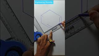
Isometric Drawing
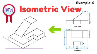
Isometric drawing is an important technique that civil engineers use to provide a clear and accurate representation of 3D objects, particularly when presenting designs for pipelines, plumbing, and architectural projects. In an isometric drawing, the three coordinate axes (x, y, and z) are oriented at equal angles of 120 degrees, allowing for a pseudo-3D appearance while still being drawn on a 2D plane.
Key Techniques
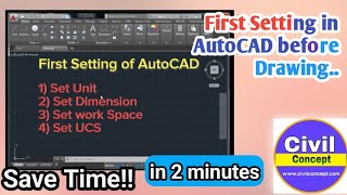
- Switch to isometric grid: One of the essential commands in AutoCAD for isometric drawing is
ISODRAFT, which allows the user to create an isometric grid within the drawing area. This grid assists in maintaining proportions and angles that are characteristic of isometric views. - Use ELLIPSE with isocircle option: When drawing circular objects such as pipes in isometric views, the
ELLIPSEcommand can be utilized with theisocircleoption. This flexibility ensures that circles appear as ellipses, maintaining visual coherence in the drawing.
Understanding isometric drawing is significant as it facilitates better comprehension of spatial relationships between components, essential for construction and design accuracy in civil engineering projects.
Youtube Videos
![How to draw isometric drawing [Drawing no 4] #shorts #shortsvideo #youtubeshorts #3d #drawing](https://img.youtube.com/vi/Ajzwvrreb-o/mqdefault.jpg)


Audio Book
Dive deep into the subject with an immersive audiobook experience.
Purpose of Isometric Drawing
Chapter 1 of 3
🔒 Unlock Audio Chapter
Sign up and enroll to access the full audio experience
Chapter Content
Isometric Drawing is used for pipelines, plumbing, and architectural presentation.
Detailed Explanation
Isometric Drawing is a technique used to represent three-dimensional objects in two dimensions. It allows the viewer to see multiple sides of an object simultaneously, making it ideal for showing complex structures like pipes and plumbing systems. This representation helps engineers and architects communicate how systems will be constructed and organized in real space.
Examples & Analogies
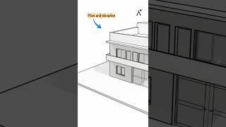
Think of an isometric drawing like viewing a house from a corner where you can see two sides at once. Just like how you intuitively understand the layout when looking at the house from that angle, isometric drawings help visualize designs from a perspective that highlights their three-dimensional nature.
Using Isometric Grid
Chapter 2 of 3
🔒 Unlock Audio Chapter
Sign up and enroll to access the full audio experience
Chapter Content
Switch to isometric grid: ISODRAFT.
Detailed Explanation
In AutoCAD, the ISODRAFT command allows users to switch to an isometric grid. This grid provides a framework for drawing more accurately in isometric views by ensuring the correct angles and proportions are maintained. The isometric grid has parallel lines that help align objects at 30-degree angles, which is essential for creating realistic isometric drawings.
Examples & Analogies
Imagine drawing a house on a piece of graph paper, but the paper has diagonal lines instead of squares. These diagonal lines show you exactly how to position your walls and roofs at the correct angles, making it simpler to create a three-dimensional effect even while working on a flat page.
Creating Ellipses for Piping
Chapter 3 of 3
🔒 Unlock Audio Chapter
Sign up and enroll to access the full audio experience
Chapter Content
Use ELLIPSE with isocircle option for pipes.
Detailed Explanation
To accurately represent cylindrical shapes like pipes in isometric drawings, you can use the ELLIPSE command combined with the isocircle option. This approach creates ellipses that visually appear circular in three-dimensional space, helping to depict the correct shape and size for the pipes within the constraints of the two-dimensional drawing.
Examples & Analogies
Visualize drawing a round bottle on a flat surface. If you draw it just as a circle, it won't look right. By drawing an ellipse, which is a flattened circle, you can show the depth of the bottle. Similarly, using the ELLIPSE tool in isometric drawing creates the illusion that the pipe has depth and structure, making it more realistic.
Key Concepts
-
Isometric Drawing: A technique for visually representing 3D objects on a 2D plane.
-
ISODRAFT: An AutoCAD command that enables the creation of an isometric grid crucial for isometric drawing.
-
ELLIPSE tool: Used to draw circles as ellipses in isometric views for accurate shape representation.
Examples & Applications
An isometric drawing for a complex plumbing layout in a high-rise building.
Visualizing the exterior of a building in isometric view to show height and dimension simultaneously.
Memory Aids
Interactive tools to help you remember key concepts
Rhymes
In isometric sights, circles are ellipses bright, draw with care, keep proportions right!
Stories
Once a young engineer faced a challenge of visualizing a complex pipeline. With the magic of the ELLIPSE command, they turned circles into ellipses, making their design clear and understandable.
Memory Tools
Remember I.G.S. – Isometric Grid Settings for drawing on point!
Acronyms
ISE - Isometric for Spatial Engagement, a reminder for the purpose of isometric drawings.
Flash Cards
Glossary
- Isometric Drawing
A method of visually representing three-dimensional objects in two dimensions, where the axes are oriented at equal angles.
- ISODRAFT
An AutoCAD command used to set up isometric drawing grids.
- ELLIPSE
An AutoCAD command used to create ellipses, particularly useful for representing circles in isometric views.
Reference links
Supplementary resources to enhance your learning experience.