
Polar Coordinates
Enroll to start learning
You’ve not yet enrolled in this course. Please enroll for free to listen to audio lessons, classroom podcasts and take practice test.
Interactive Audio Lesson
Listen to a student-teacher conversation explaining the topic in a relatable way.
Understanding Polar Coordinates
🔒 Unlock Audio Lesson
Sign up and enroll to listen to this audio lesson

Today, we are going to explore polar coordinates. Can anyone tell me what they might think these coordinates involve?

I think they have something to do with angles and distances, right?
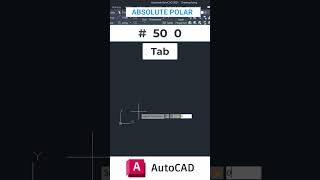
Exactly! Polar coordinates use a distance and an angle to locate a point. The format is `@distance<angle`. For example, if I want to place a point 10 units away at a 45-degree angle, I would write `@10<45`. This is very useful for inclined lines.

How does that differ from absolute and relative coordinates?
Great question! Absolute coordinates are based on a fixed origin point, while relative coordinates reference the last point drawn. Polar coordinates provide a way to define points that aren't aligned to those axes, giving us flexibility in design.

Can we practice this? Like create an inclined line?
Absolutely! Let's try drawing a line using polar coordinates. Remember, the command for a line is LINE and then you will input `@distance<angle`. So, how would you enter a line 20 units at an angle of 30 degrees?

`@20<30`!
Great job! Remembering that format is key. Let's recap: polar coordinates use distance and angle to define locations in CAD, increasing our efficiency and precision. Any questions?
Applications of Polar Coordinates
🔒 Unlock Audio Lesson
Sign up and enroll to listen to this audio lesson

Let’s dive deeper into applications for polar coordinates. Can anyone think of a scenario in engineering or architecture where this might be useful?
Maybe when designing circular structures?
Exactly! Circular or inclined structures utilize polar coordinates effectively. For instance, in designing a spiral staircase, you'd need to accommodate different angles and radii. How would you start inputting a point on a circle?
We would use the radius and angle, like `@radius<angle`?
Right! Let's say we have a circle with a radius of 5 units, what is the polar coordinate for a point at 60 degrees?
`@5<60`.
Perfect! Understanding these applications helps us design more efficiently. Just remember the format and practice with various angles and distances. Recapping our session, polar coordinates are crucial for tasks involving angles and distances in our designs. Any last queries?
Common Mistakes with Polar Coordinates
🔒 Unlock Audio Lesson
Sign up and enroll to listen to this audio lesson
Now that we’ve covered how to use polar coordinates, let's discuss some common mistakes. What do you think is a typical error students may make?
Not using the `<` when specifying the angle?
Correct! The `<` sign is essential for defining the angle correctly. If you forget it, you’ll either get an error or an incorrect location. What’s another common error?
Confusing the angle notation with degrees vs radians?
Exactly! Always ensure you're using the correct unit. CAD often requires degrees, but some contexts may require radians, so clarify what’s needed. To avoid confusion, remember your mathematics conversions. Can anyone convert 45 degrees to radians?
It's π/4, right?
Correct! As we summarize, polar coordinates are a powerful tool, but attention to detail is vital. Ensuring you format correctly and use the correct measurement units will help you avoid common pitfalls. Any questions?
Introduction & Overview
Read summaries of the section's main ideas at different levels of detail.
Quick Overview
Standard
This section focuses on polar coordinates in CAD, explaining their format and how they are utilized for drawing inclined lines. It highlights the importance of angular input in precise drafting situations.
Detailed
Polar Coordinates
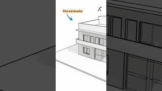
In CAD, polar coordinates play a significant role in defining points based on an angle and a distance from a reference point. The format used for entering polar coordinates in drafting commands is @distance<angle. This system is particularly useful for creating inclined lines or any element that isn't aligned with the standard axes. Understanding how to effectively use polar coordinates allows drafters to enhance precision and efficiency in architectural and engineering plans.
Youtube Videos


Audio Book
Dive deep into the subject with an immersive audiobook experience.
Introduction to Polar Coordinates
Chapter 1 of 2
🔒 Unlock Audio Chapter
Sign up and enroll to access the full audio experience
Chapter Content
Polar Coordinates are used for angular input and are ideal for drawing inclined lines in CAD.
Detailed Explanation
Polar coordinates provide a way to describe a point in space using a distance and an angle from a reference point, typically the origin. Instead of the traditional X,Y format of Cartesian coordinates, polar coordinates use the format '@distance
Examples & Analogies
Imagine you are on a playground where you want to walk to a swing. Instead of saying you need to move 3 meters to the right and 2 meters up, you can say walk 3.6 meters towards the northeast (at an angle of 45 degrees). This is similar to using polar coordinates where distance is the length of your path, and the angle indicates the direction you need to go.
Format of Polar Coordinates
Chapter 2 of 2
🔒 Unlock Audio Chapter
Sign up and enroll to access the full audio experience
Chapter Content
The format for entering polar coordinates is '@distance
Detailed Explanation
The polar coordinates format '@distance
Examples & Analogies
Think of it like giving directions to a friend in a park. Instead of saying you need to walk 5 meters north and then turn east, you simply say walk 5 meters at a 30-degree angle from where you are standing. This way, your friend can quickly understand how to get to the right location without overcomplicating the instructions.
Key Concepts
-
Polar Coordinates: A method of defining locations in CAD using distance and angle.
-
Angle Measurement: The importance of specifying angles correctly in polar coordinates.
Examples & Applications
Example 1: Using polar coordinates to draw a line at a 30-degree angle and a distance of 10 units would be entered as '@10<30'.
Example 2: To create a circle using polar coordinates, begin with a radius and angles, like entering '@5<60' for a point at 5 units away at 60 degrees.
Memory Aids
Interactive tools to help you remember key concepts
Rhymes
Polar sets you free, distance and angle, remember with glee.
Stories
A drafter named Bob used polar coordinates; he found a point by nodding at the radius and waving to the angle, creating a perfect design.
Memory Tools
For Polar Coordinates, just think: Distance is first, angle's distinct, like a compass point in sync.
Acronyms
P.A.D. - Polar, Angle, Distance.
Flash Cards
Glossary
- Polar Coordinates
A coordinate system where each point is defined by a distance from a reference point and an angle from a reference direction.
- Angular Input
The angle measurement used in polar coordinates to specify direction.
Reference links
Supplementary resources to enhance your learning experience.