
Drawing Building Plans Using CAD
Enroll to start learning
You’ve not yet enrolled in this course. Please enroll for free to listen to audio lessons, classroom podcasts and take practice test.
Interactive Audio Lesson
Listen to a student-teacher conversation explaining the topic in a relatable way.
Plan Components
🔒 Unlock Audio Lesson
Sign up and enroll to listen to this audio lesson

Today, we are going to examine the essential components of building plans drawn using CAD. Can anyone tell me what components are critical to a building plan?

I think it includes the site plan and the floor plan.
Exactly! The site plan and the floor plan are both crucial components. The site plan gives an overview of the entire area and how the building will fit into it, while the floor plan details the layout of each floor. What about section and elevation?

Those show the building's vertical layout, right?
Correct! Sections provide a view of the building's internal structure, and elevations show its external appearance. What other components can you identify?

There's also the door and window schedule.
Great! The door and window schedule outlines the types and positions of the openings in the building. Finally, what about the foundation plan?

That would show how the building is supported, right?
Absolutely! Understanding these plan components is key to effective drafting. In summary, the components include site plans, floor plans, sections, elevations, schedules, and foundation plans.
Drawing Procedure
🔒 Unlock Audio Lesson
Sign up and enroll to listen to this audio lesson

Now that we've covered the components, let's dive into the procedure for drawing a residential building. What do you think is the first step?
Drawing the plot boundary?
Correct! Establishing the plot boundary defines the lot size and is crucial for the layout. Next, what comes after that?
Making the wall layout?
Right again! The wall layout should be drawn on separate layers for clarity. Why do you think creating layers is important?
It helps separate different elements, right?
Exactly! After the wall layout, we need to insert blocks - who can tell me what blocks are?
They're reusable symbols for things like doors and windows!
Perfect! Blocks streamline the process. Next step?
Adding dimensions and labels?
Yes! Proper dimensioning and labeling are vital for clarity. Then we apply hatching for materials to make the plan more legible visually. Finally, we create elevation and section views before plotting to scale. This process ensures you produce accurate and informative building plans.
Importance of Plotting to Scale
🔒 Unlock Audio Lesson
Sign up and enroll to listen to this audio lesson
Before we finish, let's talk about the importance of plotting drawings to scale. Why is this crucial?
If the drawing is not to scale, it won't represent the actual dimensions properly!
Exactly right! When drawing buildings, having the correct scale is essential for accurate representation in construction. Can anyone explain how plotting allows for different views?
You can use layouts to show multiple views at different scales.
Correct! Using layouts for multiple views enhances understanding. Remember, ensuring all elements are to scale helps everyone involved in the construction process.
So, understanding the drawing procedure is fundamental!
Absolutely! Each step is crucial for creating comprehensive and accurate building plans.
Introduction & Overview
Read summaries of the section's main ideas at different levels of detail.
Quick Overview
Standard
This section details the key components involved in drawing building plans, including site plans, floor plans, and important documents like door and window schedules. It also presents a straightforward procedure to draw plans for a residential building using CAD software.
Detailed
Drawing Building Plans Using CAD
This section emphasizes the crucial components and methodologies for creating building plans through CAD (Computer-Aided Drafting) software, focusing particularly on civil engineering applications. Key components of building plans include:
- Site plan: a detailed representation of the entire area, including boundaries and placement of structures within the land.
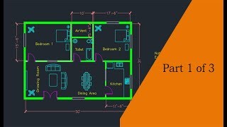
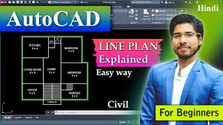
- Floor plan: outlines the layout of individual floors within the building, showcasing the arrangement of rooms and spaces.
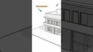
- Section and elevation: provide vertical and horizontal views of the structure, allowing for a comprehensive understanding of its form and layout.
- Door and window schedules: lists specifications and locations of openings in the building, essential for both construction and future maintenance.
- Foundation plan: outlines the structural base upon which the building is erected, detailing its design and dimensions.
The procedure for drawing a residential building involves several steps:
1. Drawing the plot boundary to define the lot size.
2. Creating the wall layout on separate layers for clarity and organization.
3. Inserting blocks to represent doors, windows, and sanitary fixtures to simplify the drawing process.
4. Adding dimensions and labels for better comprehension and construction guidance.
5. Applying hatching to indicate different materials used within the plan, enhancing the visual richness of the drawing.
6. Creating elevation and section views based on the floor plan for further documentation.
7. Utilizing layouts for properly plotting the drawing to scale, which is crucial for presentation and construction purposes.
Understanding these components and the outlined procedure enhances a civil engineer's ability to produce accurate and efficient building plans using CAD software.
Youtube Videos

Audio Book
Dive deep into the subject with an immersive audiobook experience.
Plan Components
Chapter 1 of 2
🔒 Unlock Audio Chapter
Sign up and enroll to access the full audio experience
Chapter Content
- Site plan
- Floor plan
- Section and elevation
- Door and window schedule
- Foundation plan
Detailed Explanation
This chunk lists the essential components involved in creating building plans using CAD. Each component plays a specific role in conveying the necessary information about the design and functionality of a building.
- Site Plan: This shows the entire area where the building will be constructed, including the location of the building on the site and surrounding elements like landscaping.
- Floor Plan: A detailed view of a single level of the building, illustrating walls, doors, rooms, and dimensions.
- Section and Elevation: These represent vertical slices through the building (section) or the exterior views (elevation), providing insights into height and aesthetics.
- Door and Window Schedule: This is a list or table that specifies the type and size of doors and windows used in the building.
- Foundation Plan: This part shows the structure's foundation, detailing how it will support the building above it.
Examples & Analogies
Imagine building a complex Lego structure. First, you need a blueprint (site plan) showing where each section will go. Then, as you design each layer, you need a detailed plan for each floor (floor plan), a view of how tall it will be (elevation), and which blocks (doors and windows) go where. Finally, you have to ensure the base is stable enough to support the entire structure (foundation plan).
Drawing Procedure for a Residential Building
Chapter 2 of 2
🔒 Unlock Audio Chapter
Sign up and enroll to access the full audio experience
Chapter Content
- Draw plot boundary
- Draw wall layout with layers
- Insert blocks for doors, windows, sanitary fixtures
- Add dimensions and labels
- Apply hatching for materials
- Create elevation and section from plan
- Use layout for plotting to scale
Detailed Explanation
This section outlines a step-by-step approach to drawing a residential building plan using CAD. Each step is important for effectively conveying the design to contractors and builders.
- Draw Plot Boundary: Start by marking the area of the site where construction will occur. This establishes the limits of your design.
- Draw Wall Layout with Layers: Use different layers to represent various elements; for instance, walls can be on one layer while furniture might be on another, ensuring clarity.
- Insert Blocks for Doors, Windows, Sanitary Fixtures: Using pre-made blocks speeds up the process and ensures consistency across the plans.
- Add Dimensions and Labels: Clearly label dimensions to provide exact measurements for construction.
- Apply Hatching for Materials: Use hatching patterns to distinguish different materials in the design, like solid for concrete and patterns for bricks.
- Create Elevation and Section from Plan: These additional views help visualize the building from different angles and provide valuable detailing.
- Use Layout for Plotting to Scale: Finally, preparing the plan for printing on paper in the correct scale ensures it can be easily read by builders.
Examples & Analogies
Think of creating a recipe for baking a cake. First, you need to define the size of your cake (plot boundary). Then, layout your ingredients and layers of the cake (walls) and add decorations (blocks for doors, windows). As you write the recipe, you add measurements (dimensions and labels) and describe the baking method (hatching for materials). Finally, you format the recipe for sharing with friends (plotting to scale) so they can replicate it perfectly.
Key Concepts
-
Site Plan: A representation of the site layout, boundaries, and surrounding environment.
-
Floor Plan: Contains the layout of rooms and dimensions for each floor.
-
Section View: Allows examination of interior structural details through a vertical slice of the plan.
-
Elevation: Depicts the exterior look of a building, crucial for aesthetic understanding.
-
Hatching: Used in plans to specify materials visually.
Examples & Applications
A typical residential building plan includes separate layouts for each floor, a site plan depicting neighboring structures, and sections to highlight the vertical structure.
In a CAD drawing, layers can distinguish between different materials like walls or furniture; hatching illustrates this distinction.
Memory Aids
Interactive tools to help you remember key concepts
Rhymes
In a building plan, layers are neat, each part in its place makes it complete.
Stories
Imagine a builder preparing for a big project. First, they sketch the site, marking the clear boundaries. Next, they draw the walls between rooms, making sure each one has its space. Finally, they sprinkle details like windows and doors with care, ensuring the vision is complete and fair!
Memory Tools
F-S-S-D-W-F - Floor Plan, Section View, Dimension labels, Window schedule, Foundation plan.
Acronyms
S-F-S-E - Site plan, Floor plan, Section, Elevation.
Flash Cards
Glossary
- Site Plan
A detailed representation of the entire site, showing the boundaries and layout of the building.
- Floor Plan
A drawing that outlines the layout of rooms, spaces, and functions for each floor of the building.
- Section View
A vertical cut-through view of the building showing heights and internal structure.
- Elevation
A flat representation of the front or side of a building, usually depicting height and detail.
- Hatching
A technique used in CAD to represent different materials visually through patterns.
Reference links
Supplementary resources to enhance your learning experience.