
Drawing Procedure (Example: Residential Building)
Enroll to start learning
You’ve not yet enrolled in this course. Please enroll for free to listen to audio lessons, classroom podcasts and take practice test.
Interactive Audio Lesson
Listen to a student-teacher conversation explaining the topic in a relatable way.
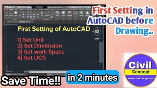
Understanding CAD Drawing Basics.
🔒 Unlock Audio Lesson
Sign up and enroll to listen to this audio lesson

Let's start with the plot boundary. It's crucial as it defines the outlined area of our building project. Can anyone tell me why it's important to clearly mark this boundary?

I think it shows the limits of where the building will stand?

And it helps in planning the space efficiently!
Exactly! Clearly marking the plot boundary not only sets spatial limits but also aids in zoning compliance. Remember, we represent this as a closed shape in CAD. Here's a mnemonic: 'Boundaries Bring Budding Buildings (4B)'. This can help you remember the sequence of steps we take with the plot.
Wall Layout and Layer Management.
🔒 Unlock Audio Lesson
Sign up and enroll to listen to this audio lesson

Once the boundary is established, the next step is drawing the wall layout. Why do you think layers are important here?

Maybe to keep different elements organized?

Yeah! It helps us control visibility for complex designs.
Absolutely! Using layers allows us to separate different elements like walls, plumbing, and electrical outputs. A good acronym to remember layers is L.O.V.E: **L**ayers **O**rganize **V**isuals **E**ffectively.
Inserting Blocks and Integrating Dimensions.
🔒 Unlock Audio Lesson
Sign up and enroll to listen to this audio lesson
Next, we insert blocks for doors, windows, and fixtures. What might be the benefit of using blocks rather than drawing each item from scratch?
I guess it saves time and makes everything consistent!
Plus, it makes the file size smaller, right?
Exactly! Blocks help maintain consistency and reduce file size. Then we add dimensions to our drawing. A quick mnemonic here is 'Don't Forget Dimensions (D.F.D)' to remind you to always annotate your designs.
Introduction & Overview
Read summaries of the section's main ideas at different levels of detail.
Quick Overview
Standard
The drawing procedure for a residential building plan in CAD involves several sequential steps, including setting the plot boundaries, drawing wall layouts, inserting necessary elements like doors and windows, adding dimensions, applying material hatching, creating elevation views, and preparing layouts for plotting.
Detailed
Drawing Procedure for a Residential Building
The drawing procedure for a residential building using CAD consists of several critical steps:
- Draw Plot Boundary: Begin by delineating the plot's borders, which provides the base structure for the building outline.
- Draw Wall Layout with Layers: Utilize the layering system to distinguish different components of the layout, ensuring clarity and organization.
- Insert Blocks for Doors, Windows, and Sanitary Fixtures: Utilize predefined block elements for efficiency, ensuring consistency and standardization in the design.
- Add Dimensions and Labels: Annotate the drawing with essential measurements and identifiers for clarity and ease of interpretation.
- Apply Hatching for Materials: Use hatching techniques to signify different materials used in construction, providing visual differentiation in the plans.
- Create Elevation and Section from Plan: Develop additional views from the main floor plan to illustrate vertical dimensions and structural characteristics.
- Use Layout for Plotting to Scale: Prepare the final drawing for printing by ensuring it adheres to scale specifications suitable for physical reproduction.
These steps not only streamline the drafting process but also enhance accuracy, facilitate collaboration, and ensure comprehensive representation of the building’s design.
Youtube Videos


Audio Book
Dive deep into the subject with an immersive audiobook experience.
Step 1: Draw Plot Boundary
Chapter 1 of 7
🔒 Unlock Audio Chapter
Sign up and enroll to access the full audio experience
Chapter Content
- Draw plot boundary
Detailed Explanation
The first step in drawing a residential building plan is to establish the plot boundary. This means creating a defined area on your CAD drawing that represents the limits of the property where the building will be situated. This boundary serves as a reference point for all other elements of the design and ensures that the structure fits within the legal and physical confines of the land.
Examples & Analogies
Think of drawing a plot boundary like outlining the edges of a puzzle piece. Without that outline, you cannot accurately place the pieces (or in this case, the building elements) inside.
Step 2: Draw Wall Layout with Layers
Chapter 2 of 7
🔒 Unlock Audio Chapter
Sign up and enroll to access the full audio experience
Chapter Content
- Draw wall layout with layers
Detailed Explanation
Next, you will create the wall layout. This involves using the CAD software to draw the lines that represent the walls of the building. Utilizing layers in CAD is crucial here, as it allows you to organize different elements of the drawing. For example, you might have a separate layer for the walls, another for doors, and another for electrical layouts. This organization helps improve the clarity and manageability of your design.
Examples & Analogies
Imagine building a model with layers: just as you would add a layer for the foundation, walls, and roof, in CAD, each component gets its own layer to prevent confusion and enhance visibility.
Step 3: Insert Blocks for Doors, Windows, Sanitary Fixtures
Chapter 3 of 7
🔒 Unlock Audio Chapter
Sign up and enroll to access the full audio experience
Chapter Content
- Insert blocks for doors, windows, sanitary fixtures
Detailed Explanation
In this step, you will insert blocks into your drawing for various fixtures like doors, windows, and sanitary items. Blocks are pre-drawn symbols that can be reused throughout your drawings. Using blocks saves time and ensures consistency in the design elements. For instance, when you insert a door block, it is already designed to the correct specifications, which improves the accuracy of your final plan.
Examples & Analogies
Think of blocks like using cookie cutters for baking. Each cookie cutter shape (block) can be used multiple times, ensuring that your cookies (or in this case, fixtures) are all uniform and accurate without having to redraw each one from scratch.
Step 4: Add Dimensions and Labels
Chapter 4 of 7
🔒 Unlock Audio Chapter
Sign up and enroll to access the full audio experience
Chapter Content
- Add dimensions and labels
Detailed Explanation
Once the main components are in place, it’s important to add dimensions to your drawing. Dimensions indicate the size and distance between elements in the plan. Labels provide context and details about each part of the structure, such as identifying which rooms are which or specifying materials. Clear dimensions and labels are essential for anyone interpreting the plans to understand the scale and layout of the building.
Examples & Analogies
Adding dimensions and labels is similar to adding a legend or scale to a map. Just like a map needs clear markers to guide you, your building plan requires dimensions and labels to guide construction workers and architects.
Step 5: Apply Hatching for Materials
Chapter 5 of 7
🔒 Unlock Audio Chapter
Sign up and enroll to access the full audio experience
Chapter Content
- Apply hatching for materials
Detailed Explanation
Hatching refers to the patterned filling applied to areas in your drawing to represent different materials, such as concrete, brick, or landscaping. Applying hatching helps visually distinguish between these materials, enhancing the overall comprehensibility of the plan. In CAD, hatching can be customized in terms of scale and pattern to properly reflect the material usage.
Examples & Analogies
Applying hatching is like using a color code on a map. Just as you may use different colors to indicate forests, water, and urban areas, hatching indicates various construction materials, making it easier for builders to understand the plan.
Step 6: Create Elevation and Section from Plan
Chapter 6 of 7
🔒 Unlock Audio Chapter
Sign up and enroll to access the full audio experience
Chapter Content
- Create elevation and section from plan
Detailed Explanation
This step involves producing elevation and section views based on the previously drawn floor plan. Elevations represent how the building will look from each side, while sections show internal structures as if it was sliced through a particular point. These views are critical because they provide additional details that the floor plan alone cannot convey.
Examples & Analogies
Creating elevation and section views is like taking different angles of a photo. Just as you need to capture images from various perspectives to fully understand a landscape, these views help express the building’s dimensions and internal layout more completely.
Step 7: Use Layout for Plotting to Scale
Chapter 7 of 7
🔒 Unlock Audio Chapter
Sign up and enroll to access the full audio experience
Chapter Content
- Use layout for plotting to scale
Detailed Explanation
The final step is using the layout feature in your CAD software to prepare the drawing for printing or plotting. This involves arranging the drawing on a standardized paper size and ensuring that the scale is appropriate for printing. Proper scaling ensures that all dimensions match the actual size of the building when construction commences.
Examples & Analogies
Think of this step as setting up a photo for framing. Just as you need to ensure the picture fits perfectly within the frame and is the right size to display correctly, your drawing must be plotted to scale so that builders can accurately interpret the plan on physical paper.
Key Concepts
-
Drawing Procedure: Steps to create a residential building plan using CAD.
-
Layer Management: Organizing drawing elements using layers for better clarity.
-
Using Blocks: Incorporating reusable symbols and components into designs.
-
Dimensioning: Adding measurements for clarity in plans.
-
Plotting Techniques: Preparing drawings for printing to the correct scale.
Examples & Applications
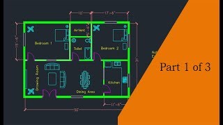
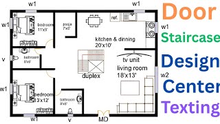
A plot boundary could represent a 50 x 100 plot for a standard residential lot.
A wall layout might indicate the placement of interior and exterior walls along with their thickness.
Memory Aids
Interactive tools to help you remember key concepts
Rhymes
In drawing plans, we set the bounds, for building dreams on solid grounds.
Stories
Imagine a plot of land where a family dreams to build their future. The first thing they do is outline their space—this is their plot boundary, ensuring their dreams remain within the lines.
Memory Tools
To remember the steps of drawing a plan: Plot, Walls, Blocks, Dimensions, Hatching, Elevations, Layout (PWBDHEL).
Acronyms
'B.L.A.D.E.' for the drawing process
**B**oundaries
**L**ayers
**A**ctions (blocks)
**D**imensions
and **E**levations.
Flash Cards
Glossary
- Plot Boundary
The designated outline of the property on which a building is to be constructed.
- Layer Management
Organizing different elements in a CAD drawing into distinct layers for clarity and control.
- Blocks
Reusable elements in CAD that represent drawings like doors, windows, etc., which streamline the drawing process.
- Hatching
A method used in CAD to fill areas with patterns representing different materials.
- Dimensions
Annotations that provide measurements and spatial relationships between objects in a drawing.
Reference links
Supplementary resources to enhance your learning experience.