
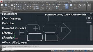
Rectangle Command
Enroll to start learning
You’ve not yet enrolled in this course. Please enroll for free to listen to audio lessons, classroom podcasts and take practice test.
Interactive Audio Lesson
Listen to a student-teacher conversation explaining the topic in a relatable way.
Introduction to the Rectangle Command
🔒 Unlock Audio Lesson
Sign up and enroll to listen to this audio lesson

Today, we’re discussing the Rectangle Command in CAD. This command is crucial because it allows us to create rectangles, which are fundamental shapes in architectural and civil designs.

How do we actually use the Rectangle Command?
Great question! To use the Rectangle Command, you simply type `RECTANGLE` and then specify the coordinates of the first corner followed by the opposite corner.

Can you give us an example of those coordinates?
Sure! For instance, if we specify the first corner at (0,0) and the opposite corner at (100,50), we’ll create a rectangle that is 100 units wide and 50 units tall.

That sounds simple enough! Is there anything special we need to remember when drawing rectangles?
Yes, remember to always check your units! This will ensure that your rectangle is drawn to the correct scale.

So, we should always keep a consistent unit of measurement in mind?
Exactly! Consistency in units leads to more accurate designs.
To summarize, the Rectangle Command is fundamental for defining rectangular shapes in CAD. Make sure to specify your corners correctly and always be aware of your measurement units.
Practical Applications of the Rectangle Command
🔒 Unlock Audio Lesson
Sign up and enroll to listen to this audio lesson

Now that we understand how to use the Rectangle Command, let’s talk about where we can apply this tool in our projects.
Are there specific types of drawings that use rectangles frequently?
Absolutely! Rectangles are frequently used in site plans, floor plans, and various structures, such as buildings and roads.
What if we need to create different shapes incorporating rectangles?
Good point! Rectangles can be combined with other shapes in CAD to create more complex designs. Using the Rectangle Command is often the first step in such combinations.
So rectangles are versatile in design?
Exactly! Their versatility is why they are so commonly used. Always think of rectangles as building blocks in CAD.
To summarize, rectangles are essential in CAD drafts, allowing for the efficient creation of various design elements in civil engineering.
Intersection with Other Commands
🔒 Unlock Audio Lesson
Sign up and enroll to listen to this audio lesson
Let's explore how the Rectangle Command works alongside other commands in CAD, like Trim and Extend.
Can rectangles be modified using those commands?
Yes! After creating a rectangle, you can use Trim to remove any unwanted sections or Extend to adjust its size by meeting another shape.
This sounds like it simplifies the drafting process!
Exactly! By combining commands, we can significantly streamline our workflow while enhancing precision. Always consider how you can combine commands.
In conclusion, using the Rectangle Command with others can simplify your drafting tasks, making it easier to create complex shapes and layouts.
Introduction & Overview
Read summaries of the section's main ideas at different levels of detail.
Quick Overview
Standard
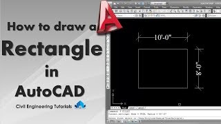
The Rectangle command is a fundamental drafting tool in CAD that allows users to create rectangular shapes by defining two opposite corners. Mastering this command is vital for civil engineering projects where precise measurements and layout are critical.
Detailed
Rectangle Command in CAD
The Rectangle Command is a basic yet essential tool in Computer-Aided Drafting (CAD) that allows designers to create rectangles quickly and accurately. In civil engineering, this command is utilized to establish boundaries for structures and layout spaces in designs.
Key Points:
- Command Usage: The command is invoked using
RECTANGLE. - Point Specification: The user specifies the first corner and then the opposite corner, allowing for precision in placement and size.
- Importance: Mastery of this command is crucial for effective drafting in civil engineering, as rectangles are commonly used in various plans and layouts, including site plans, building layouts, and more.
The efficiency that comes with the Rectangle command enhances the overall speed and accuracy of the drafting process in civil engineering projects.
Youtube Videos

Audio Book
Dive deep into the subject with an immersive audiobook experience.
Command Overview
Chapter 1 of 4
🔒 Unlock Audio Chapter
Sign up and enroll to access the full audio experience
Chapter Content
Command: RECTANGLE
Detailed Explanation
The rectangle command in CAD is accessed by typing 'RECTANGLE' into the command line. This command is specifically designed for drawing rectangles. It allows you to define the geometry of the rectangle by specifying two opposite corners.
Examples & Analogies
Think of this as drawing a rectangle on graph paper. You would first mark one corner at a specific point and then find the diagonal corner to complete the rectangle. The 'RECTANGLE' command does this for you in a digital space.
Specifying the First Corner
Chapter 2 of 4
🔒 Unlock Audio Chapter
Sign up and enroll to access the full audio experience
Chapter Content
Specify first corner: 0,0
Detailed Explanation
When you initiate the rectangle command, you will be prompted to specify the first corner of the rectangle. In this case, you enter the coordinates '0,0', which means that the first corner is located at the origin of the coordinate system—the bottom left corner of your draughting space.
Examples & Analogies
Imagine you are laying the foundation for a rectangular garden. The point '0,0' is where you start digging in the soil, creating your first corner and defining where the garden will be placed.
Specifying the Opposite Corner
Chapter 3 of 4
🔒 Unlock Audio Chapter
Sign up and enroll to access the full audio experience
Chapter Content
Specify opposite corner: 100,50
Detailed Explanation
After defining the first corner, the next step is to specify the opposite corner of the rectangle. In this example, entering '100,50' means that you are extending the rectangle to the right by 100 units and upward by 50 units. This position will define the upper right corner of the rectangle.
Examples & Analogies
Continuing with the garden analogy, specifying '100,50' is like deciding how wide and tall you want the garden to be. By marking the opposite corner, you effectively create the outline of your gardening plot.
Understanding Rectangle Dimensions
Chapter 4 of 4
🔒 Unlock Audio Chapter
Sign up and enroll to access the full audio experience
Chapter Content
Rectangle is defined by two opposite corners.
Detailed Explanation
A rectangle is uniquely determined by two opposite corners in CAD. The first corner positioned at '0,0' and the second corner at '100,50' gives the rectangle its width and height. The first coordinate defines the starting point, while the second coordinate determines the extent and dimensions of the shape.
Examples & Analogies
Picture making a rectangular pizza; the two corners you define dictate both the size and the shape of the pizza. Just as those corners are crucial for achieving the desired pizza dimensions, specifying the corners in CAD shapes your rectangle precisely.
Key Concepts
-
Using the Rectangle Command to create precise shapes.
Examples & Applications
Drawing a rectangular plot for a building using coordinates (0,0) and (100,50).
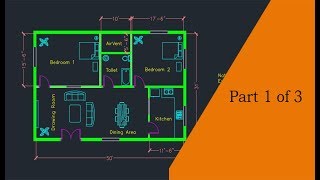
Creating furniture layouts using rectangles in a floor plan.
Memory Aids
Interactive tools to help you remember key concepts
Rhymes
To draw a rectangle, it’s really quite clear, two corners you click, and we’ll give a cheer!
Stories
Imagine a builder using a measuring tape to mark out where to draw rectangles for walls, ensuring they fit perfectly in the space.
Memory Tools
R.C. for Rectangle Command - Remember 'R' for Rectangle and 'C' for Command to recall this command.
Acronyms
RECT
Remember Every Corner Together - This helps remember you need two corners for the Rectangle Command.
Flash Cards
Glossary
- Rectangle Command
A CAD command used to draw rectangles by specifying two opposite corners.
- Coordinates
The set of values that define a point's position in a specified system.
- CAD
Computer-Aided Design; software used for drafting and designing.
Reference links
Supplementary resources to enhance your learning experience.